2 tool data, 2 t ool d a ta – HEIDENHAIN TNC 310 (286 140) User Manual
Page 57
45
HEIDENHAIN TNC 310
5.2 Tool Data
You usually program the coordinates of path contours as they are
dimensioned in the workpiece drawing. To allow the TNC to
calculate the tool center path — i.e. the tool compensation — you
must also enter the length and radius of each tool you are using.
Tool data can be entered either directly in the part program with
TOOL DEF or (and) separately in tool tables. The TNC will consider
all of the data entered when executing the part program.
Tool number
Each tool is identified by a number between 0 and 254.
The tool number 0 is automatically defined as the zero tool with the
length L=0 and the radius R=0. In tool tables, tool 0 should also be
defined with L=0 and R=0.
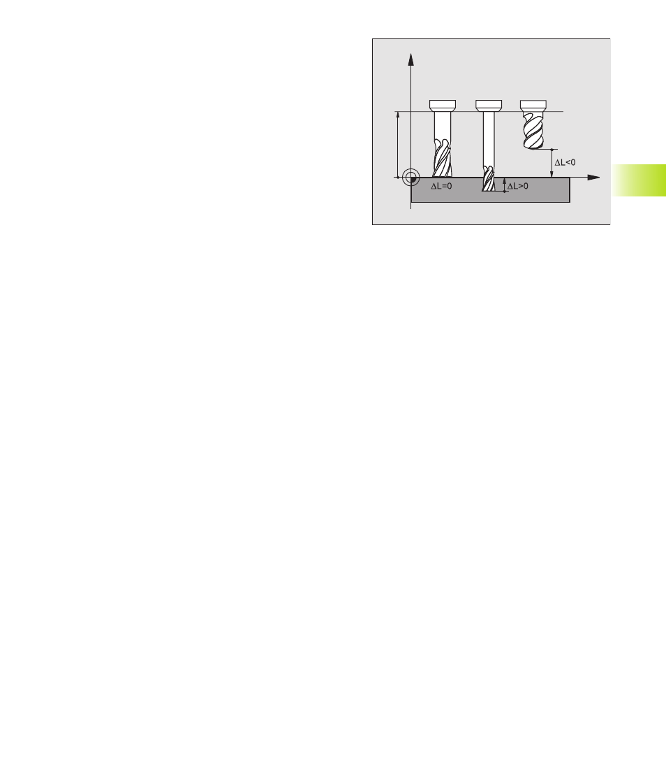
Tool length L
There are two ways to determine the tool length L:
1 The length L is the difference between the length of the tool and
that of a zero tool L
0
.
For the algebraic sign:
■
The tool is longer than the zero tool
L>L
0
■
The tool is shorter than the zero tool:
L<L
0
To determine the length:
ú
Move the zero tool to the reference position in the tool axis
(e.g. workpiece surface with Z=0).
ú
Set the datum in the tool axis to 0 (datum setting).
ú
Insert the desired tool.
ú
Move the tool to the same reference position as the zero tool.
ú
The TNC displays the difference between the current tool and the
zero tool.
ú
Enter the value in the TOOL DEF block or in the tool table by
pressing the „ACTUAL POSITION“ key
2 If you determine the length L with a tool presetter, this value can
be entered directly in the TOOL DEF block without further
calculations.
5.2 T
ool D
a
ta
Z
X
L
0