Simulation flow, Simulation flow –20, R to – Altera PCI Compiler User Manual
Page 230
4–20
User Guide Version 11.1
Altera Corporation
PCI Compiler
October 2011
Simulation Flow
Simulation Flow
This section describes the simulation flow using Altera PCI testbench.
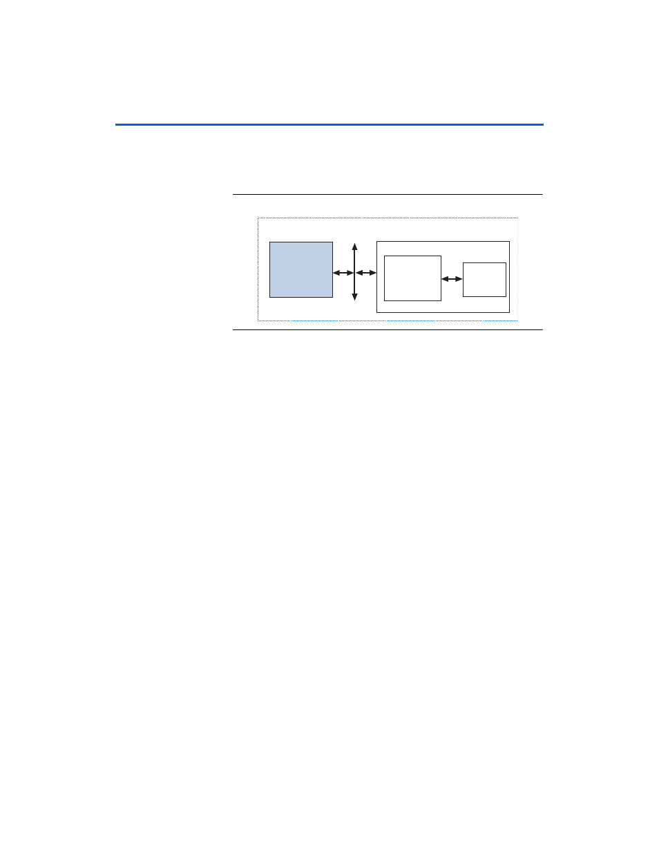
shows the block diagram of a typical verification environment
using the PCI testbench.
Figure 4–5. Typical Verification Environment Using the PCI Testbench
The simulation flow using Altera PCI testbench comprises the following
steps.
1.
Use IP Toolbench to specify the PCI MegaCore function
configuration space parameters and generate an
IP functional simulation model of your custom PCI MegaCore
function.
2.
Set the initialization parameters, which are defined in the master
transactor model source code. These parameters control the address
space reserved by the target transactor model and other PCI agents
on the PCI bus.
3.
The master transactor defines the procedures (VHDL) or tasks
(Verilog HDL) needed to initiate PCI transactions in your testbench.
Add the commands that correspond to the transactions you want to
implement in your tests to the master transactor model source code.
At a minimum, you must add configuration commands to set the
BAR for the target transactor model and write the configuration
space of the PCI MegaCore function. Additionally, you can add
commands to initiate memory or I/O transactions to the PCI
MegaCore function.
Refer to
for more information about the user
commands.
Your
Application
Design
IP Functional
Simulation Model
of an Altera PCI
MegaCore
Function
Altera Device
PCI Bus
Altera PCI Testbench
Testbench
Modules