Fronius Energy Package User Manual
Page 26
24
Controls, connec-
tions and indica-
tors on the
system monitor-
ing unit
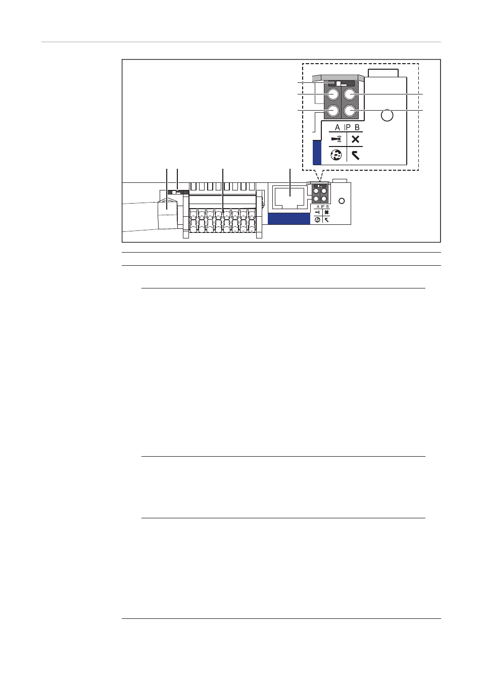
No. Function
(1)
IP switch
For switching the IP address:
Switch position A
Default IP address with opening of the WLAN access point
System monitoring uses the set IP address 169.254.0.180 to establish a direct
connection to a PC via LAN.
Setting the IP switch to position A also opens an access point to enable a direct
WLAN connection to the system monitoring datalogger.
Access data for this access point:
Network name: FRONIUS_239.XXXXXX
Code: 12345678
System monitoring can be accessed by:
-
Using the DNS name “http://datamanager”
-
Using the IP address 169.254.0.180 for the LAN interface
-
Using the IP address 192.168.250.181 for the WLAN access point
Switch position B
Assigned IP address
System monitoring uses an assigned IP address (factory setting: dynamic (DH-
CP))
The IP address can be set on the system monitoring web page.
(2)
WLAN LED
-
Flashing green: System monitoring is in Service mode
(IP switch on the system monitoring plug-in card is in position A or Service
mode has been activated via the inverter display, the WLAN access point is
open)
-
Steady green: WLAN connection established
-
Flashing alternately green/red: WLAN access point has timed out following ac-
tivation (1 hour)
-
Steady red: No WLAN connection
-
Flashing red: Faulty WLAN connection
(5)
(1)
(6)
(7)
(8)
(9)
(4)
(2)
(3)
LAN