Fronius Energy Package User Manual
Page 27
25
EN
(3)
Solar.web connection LED
-
Steady green: Fronius Solar.web connection established
-
Steady red: Fronius Solar.web connection is required but has not been estab-
lished
-
Not lit: No Fronius Solar.web connection is required or the option for sending
data to Fronius Solar.web has been deactivated
(4)
Supply LED
-
Steady green: Internal communication system is providing an adequate power
supply; system monitoring is ready for use
-
Not lit: No power is being supplied by the internal communication system
-
Flashing red: Update in progress
IMPORTANT! Never interrupt the power supply while an update is in progress.
-
Steady red: Update failed
(5)
Connection LED
-
Steady green: Good connection within the internal communication system
-
Steady red: Connection within the internal communication system has been in-
terrupted
(6)
LAN connection
Ethernet interface, colour-coded blue, for connecting the Ethernet cable
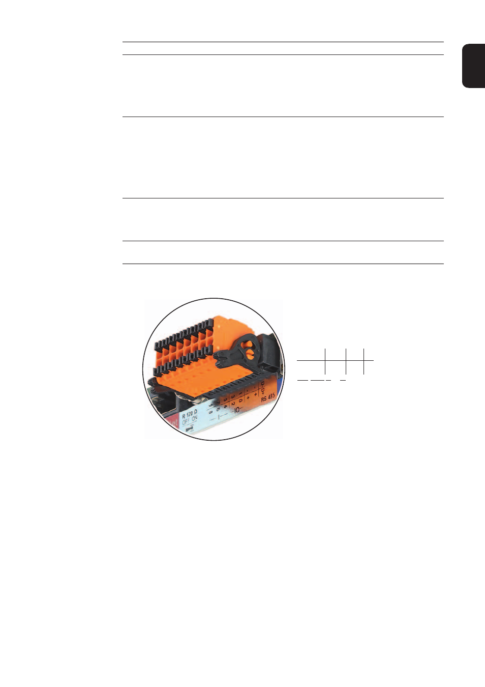
(7)
I/Os
Digital inputs and outputs
Modbus RTU 2-wire (RS485):
D-
Modbus data -
D+
Modbus data +
Int./ext. supply
-
GND
+
U
int
/ U
ext
Internal voltage output 12.8 V
or
input for an external supply voltage
>12.8 - 24 V DC (+ 20%)
Digital inputs: 0 - 3, 4 - 9
Voltage level: Low = min. 0 V - max. 1.8 V; high = min. 3 V - max. 24 V DC (+ 20%)
Input currents: Dependent on input voltage; input resistance = 46 kohms
No. Function
D-
-
-
1
3
5
7
9
D+
+
+
0
2
4
6
8
I IO RS485