Fronius Energy Package User Manual
Page 37
35
EN
“Power” LED (Fronius Solar Battery)
This LED is connected directly to the supply voltage of the 1st serial interface (electrical
isolation is optionally available for this supply).
“1/2/4/8 (Error No / Selected ID)” LED
If these 4 LEDs and the “State” LED all light up steady red at the same time, the error num-
ber is indicated in binary format in accordance with the table in the “Troubleshooting” sec-
tion.
“State” LED (Fronius Solar Battery)
“State” LED (Fronius Symo Hybrid)
“Power” LED (Fronius Symo Hybrid)
This LED is connected directly to the supply voltage of the interface.
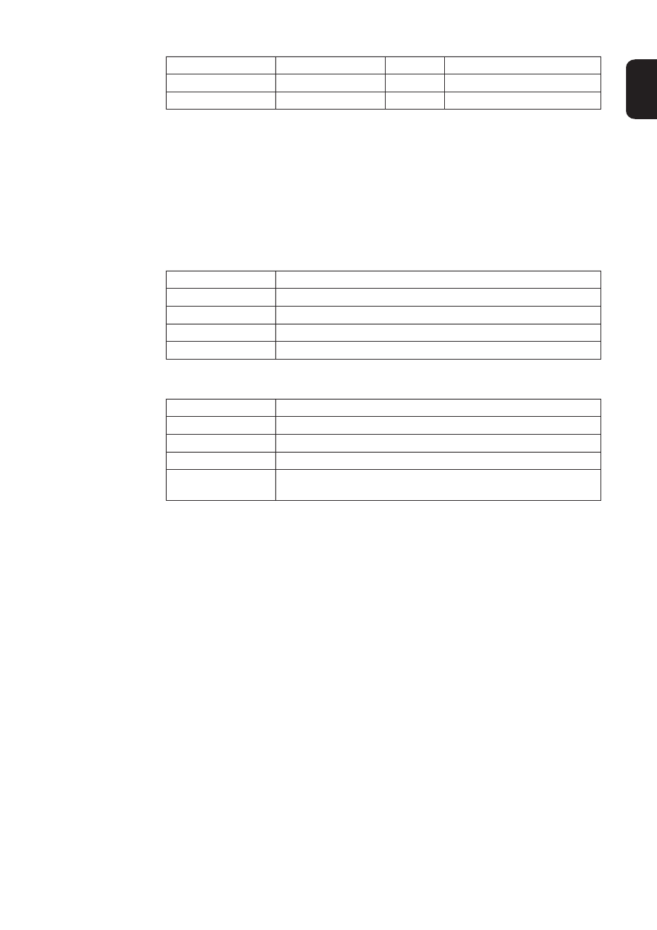
State LED
Red/green General gateway error
State LED
Red/green Inverter interface state
Power LED
Green
Inverter supply voltage
Steady green
Status OK
Flashing green
Status OK
Flashing green/red
Status OK
Steady red
General gateway error (see “Error No.” LEDs)
Flashing red
Data converter is in Configuration/Test mode
Steady green
Initialised and started
Flashing green
Initialised
Flashing green/red
-
Steady red
General bus error (system error 10)
Flashing red
Starts to flash straight after “BusStart” -> Initialisation failed
Starts to flash during actual operation -> Data error