Fronius Energy Package User Manual
Page 28
26
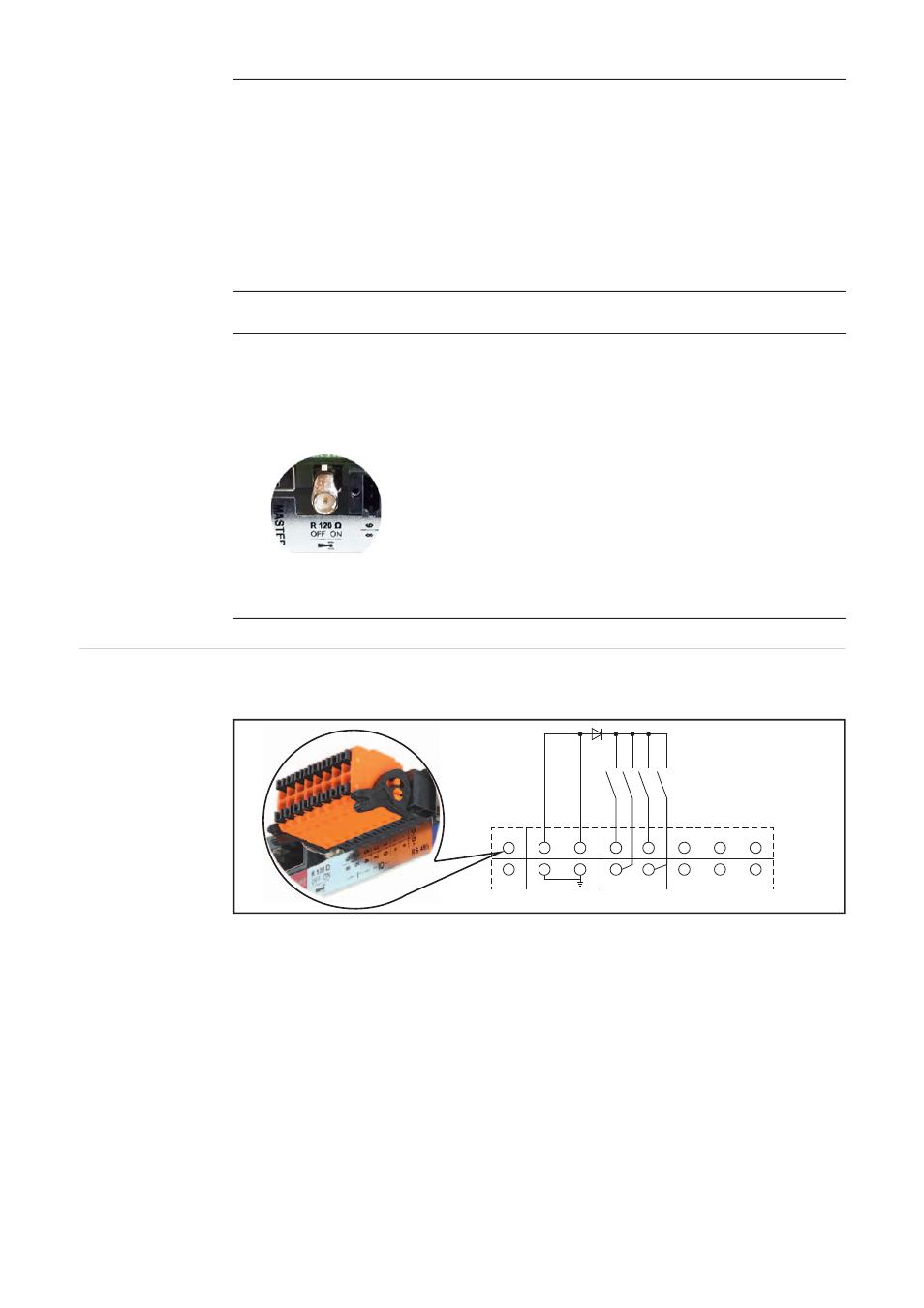
Schematic con-
nection diagrams
for I/Os
Power supplied by the system monitoring plug-in card:
Power supplied by an external power supply:
Digital outputs: 0 - 3
Switching capacity when power is supplied by the system monitoring plug-in card:
3.2 W in total for all 4 digital outputs
Switching capacity when power is supplied by an external power supply delivering
min. 12.8 - max. 24 V DC (+ 20%), connected to Uint / Uext and GND: 1 A, 12.8 -
24 V DC (depending on external power supply) for each digital output
The connection to the I/Os is established via the mating connector supplied.
(8)
Antenna socket
This is where the WLAN antenna is connected.
(9)
Modbus termination switch (for Modbus RTU)
Internal bus terminator with 120 ohm resistor (yes/no)
Switch in “on” position: 120 ohm terminating resistor active
Switch in “off” position: No terminating resistor active
IMPORTANT! On an RS485 bus, the terminating resistor on the first and last devic-
es must be active. For a detailed description, see the installation instructions.
No. Function
D-
-
-
D+
+
+
0
2
5
7
8
9
3
4
6
1