Gasboy Fuel Point PLUS Station User Manual
Page 131
5.1. Installation Highlights
5.1.1 General
When screwing the hose adaptor into the
nozzle near hose end, apply pressure to prevent
disengagement and seal the connection
according to local requirements and
regulations. Inspect the connection to verify
there is no leakage
5.1.2 OPW 11 A/B
To secure the rigid conduit to the nozzle, lift
the hand guard screw end up slightly and hook
the mounting tab to it (see Figure 3)
Figure 3. Attaching the Conduit to the Hand
Guard Screw
Install the mechanical fitting and secure it with
the spout screw
In the 11A model, the spout retaining screw
used to secure the mechanical fitting is located
on the bottom side of nozzle. In the 11B
model, it is located on the top side (see Figure
4).
Figure 4. Releasing the Spout Retaining Screw
11A (left) & 11B (right)
Cut a small notch in the center of the scuff
guard, using a utility knife (see Figure 5) to
allow the mechanical fitting to come out
Figure 5. Cutting the Scuff Guard
5.1.3 Husky X/1A/1-8
To install the rigid conduit, place the conduit
clamp around the nozzle near spout end and
secure it using the provided screw, washers and
nut
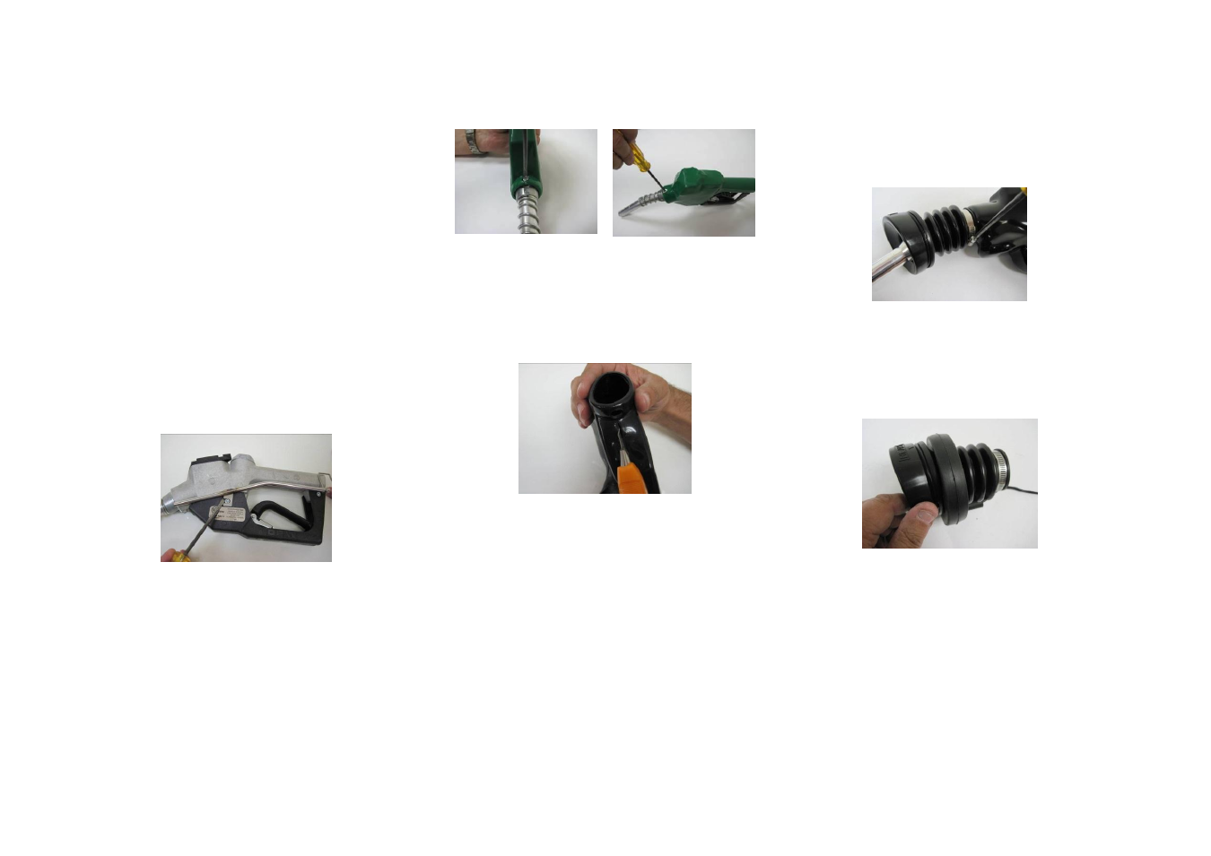
5.1.4 Healy 400/600/700/800/900
To install the round coil, proceed as follows:
1. Unscrew the bellows clamp and grip the
bellows while gently pulling to separate
them from the nozzle (see Figure 6)
Figure 6. Removing the Bellows
2. Slide the coil over the bellows from the
rear side until it reaches the Vapor Escape
Guard (see Figure 7) and replace the
bellows
Figure 7. Sliding the Coil over the Bellows
3. Verify that the Healy logo on the bellows
is aligned with the top center of the nozzle
and compress the bellows to ensure that
the coil does not impede compression (see