Led indicators, Table 5-4 - jumper settings, Table 5-5 - leds - pcb left side – Gasboy Fuel Point PLUS Station User Manual
Page 47: Table 5-6 - leds - pcb right side
Fuel Point PLUS Station Equipment Manual
47
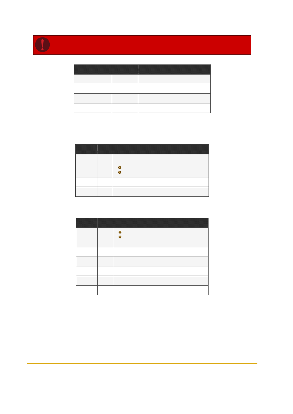
Caution: Only authorized technicians are allowed to modify jumper default settings.
Jumper #
Name
Description
J2
Watch Dog
J3
Reset
J4 (Pins 1-2)
3.3.V
SAM power 3.3V
J4 (Pins 2-3)
5V
SAM power 5V
Table 5-4 - Jumper Settings
5.5.5. LED Indicators
(See
and
LED #
Name
Description
DL2
100
Indicates communication rate:
Lit: 100 BPS
Off: 10 BPS
DL3
ACT
Blinks during active communication
DL4
LNK
Constantly lit when Ethernet is connected
Table 5-5 - LEDs - PCB left side
LED #
Name
Description
DL9
GP
Constantly lit
Blinks during data transfer over external
communication (Ethernet, RS-232, RS-485)
TAG
Not used
RST
Lights during reset
5V
Indicates that +5V is active
DL7
3V
Indicates that +3.3V is active
DL8
1V8
Indicates that +1.8V is active
Table 5-6 - LEDs - PCB Right Side