Μwnr-t installation, Post installation checklist, Maintenance 7.1. general – Gasboy Fuel Point PLUS Station User Manual
Page 133: Battery replacement
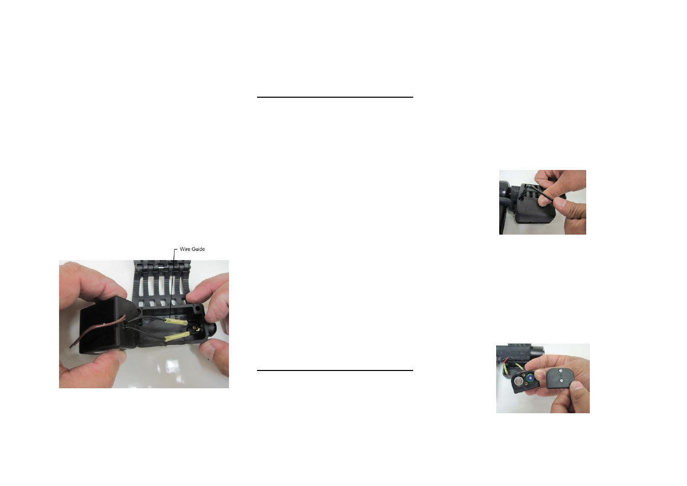
5.2. µWNR-T Installation
µWNR-T installation kits are similar to the µWNR-
B kits described above. The only difference is the
addition of an activation switch suitable for fueling
trucks implementations, since the fueling truck
movement is liable to cause unnecessary activations
of the unit. When the pushbutton is pressed, the
mechanism is prompted to search for the nearby
FuelOpass.
Proceed as follows:
Instead of shortening the activation wires,
connect them to the activation button wires
(polarity is not important). Use nylon butt
connectors and a crimping tool. Then place the
activation wires in the wire guide (see Figure
Figure 14. Connecting Activation Wires to the
Pushbutton
6. POST INSTALLATION
CHECKLIST
The μNR is supplied as ready-for- installation kit.
After assembling and programming the μNR,
switch on the dispenser and please verify that:
1. The pump switches on after the μNR identifies
the FuelOpass
2. Connections are tight and leak free
3. After installation the installer is to verify that the
hose nozzle valve fits correctly into the
dispensing device’s hose nozzle boot.
a) The hose nozzle valve shall be able to be
placed in the hose nozzle boot without falling
out;
b) The hose nozzle valve shall not be allowed to
be placed in the hose nozzle boot without
shutting down the dispenser;
c) The hose nozzle valve shall be able to be
locked in position such that the pump cannot be
started.
If the hose nozzle valve/reader combination does
not fit correctly, then the reader should be
removed and cannot be used with that hose
nozzle valve.
7. MAINTENANCE
7.1. General
The μNR does not require any cleaning or
lubrication.
Inspect regularly for visual damages.
7.2. Battery Replacement
The following should be performed by properly
trained personnel.
Warning: to reduce the risk of ignition of a
flammable atmosphere, batteries must only be
changed in an area known to be nonflammable.
1. Remove the two Allen screws that secure the
back clamp (see Figure 15) and open it
Figure 15. Opening the Back Clamp
2. .Pull out the µNozzle Reader assembly carefully,
to avoid damaging the wires
3. Release the two Phillips screws and take off the
µNR assembly lid
4. Slide the batteries out
5. Slide a new set in, following the polarity signs on
the battery compartment (see Figure 16)
Figure 16. Replacing Batteries