Service display screens -13, Service display screens – Hypertherm HD4070 Rev.8 User Manual
Page 160
MAINTENANCE
HD4070
Instruction Manual
5-13
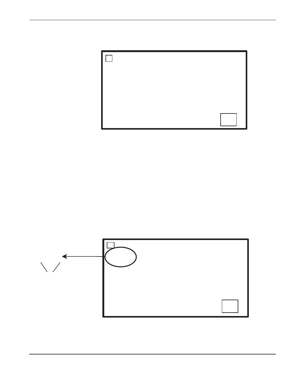
1
AMPERAGE: 000.0 AMPS
POWER CHECK: 000.0 VAC
INLET GAS 1: 000.0 PSI
INLET GAS 2: 000.0 PSI
INLET GAS 3: 000.0 PSI
STATE: 0
DATA BASE REV: 0
SOFTWARE REV: 0
NEXT
VOLTAGE: 000.0 V
STARTS: 0000000
ERRORS: 0000000
HOURS: 0000000
PORT 0
00000000
PORT 2
00000000
PORT 1
00000000
PORT 3
00000000
PORT 8
00000000
PORT 10
00000000
PORT 9
00000000
PORT 11
00000000
PORT 12
00000000
PORT 14
00000000
PORT 13
00000000
PORT 4
00000000
PORT 6
00000000
PORT 5
00000000
PORT 7
00000000
NEXT
PORT 0
00000000
Bit 0-7
17
18
Service Display Screens
Screen 17 is display only. No adjustments can be made.
Amperage- Actual arc current
Power check- Actual measure of 120VAC from control transformer
Inlet gas 1- Inlet gas pressure (not checked in idle state)
Inlet gas 2- Inlet gas pressure (not checked in idle state)
Inlet gas 3- Inlet gas pressure (not checked in idle state)
State- State of power supply
Screen 18 is display only.
Input/Output status: See table in Appendix D for details.
State 0 = Initialization
State 6 = Arc transfer
State 1 = Waiting for user to select process
State 7 = Ramp-up
State 2 = Purge
State 8 = Steady (run) state
State 3 = Idle (waiting for start)
State 9 = Ramp-down
State 4 = Preflow and IHS, if THC is present
State 10 = Final ramp-down
State 5 = Pilot arc
State 11 = Auto OFF
State 14 = Shut-down