Pc-104 test procedure -20, Pc-104 test procedure, Pc-104 dc power: pin designators – Hypertherm HD4070 Rev.8 User Manual
Page 167
MAINTENANCE
5-20
HD4070
Instruction Manual
4
PC-104 Test Procedure
1. Turn main power OFF.
2. Remove connectors from PC-104 stack in the following order:
– Board 1 J4 - Remove for access. Reconnect after all other connections are made.
– B1, J2
– B3, J1
– B4, J1 and J4
– B5, J1 and J4
– B6, J1 and J3
3. Make the following connections, using cables provided in this kit.
– B3, J1 to B7, J4
– B4, J1 to B4, J4
– B5, J1 to B5, J4
– B7, J3 to B6, J1
– B6, J3 to B7, J1
– B1, J2 to B7, J2
– Reconnect ribbon cable to B1, J4
4. Insert disk (part # 081084) into drive
5. Turn main power switch ON. Start-up will take approximately 30 seconds. After start-up LED (D1) will be yellow
and all lamps on LEDN1 will be extinguished.
6. As each board is tested the corresponding LEDN lamp will illuminate. Each lamp will be extinguished if the test
is successful. It will remain illuminated if there is a failure. The testing sequence is: CPU, COMM 3&4, FLOPPY,
FLASH, LOW I/O, HIGH I/O, ANALOG.
Each test can take 2 minutes. LED (D1) will be green if all tests pass. It will be red if there is a failure. Certain
communication failures can cause the process to freeze. If a test is taking longer than 2 minutes, re-start the power
supply.
1
2
3
4
5
6
7
8
1
2
3
4
5
6
5
4
3
2
1
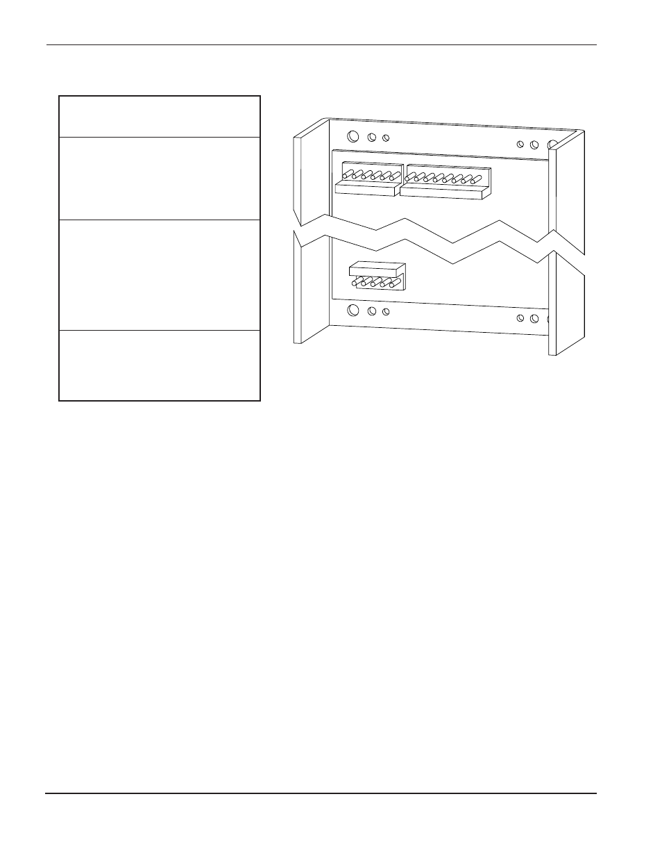
PC-104 DC Power: Pin Designators
CN2 (P106)
CN1 (J14)
Designator
Pin
Function
Number
1
-12 VDC
2
Blank
CN2
3
Blank
(P106)
4
+12 VDC
5
+12 VDC
6
Blank
1
Blank
2
Common
3
Common
CN3
4
Common
(P82)
5
+5 VDC
6
+5 VDC
7
+5 VDC
8
Blank
1
240 VAC
CN1
2
Blank
(J14)
3
Common
4
Blank
5
Ground
CN3 (P82)