LSC Lighting Redback Wallmount Operators Manual User Manual
Page 18
Menu System
Redback Wallmount Dimmer
Operator Manual V1.3
Page 14
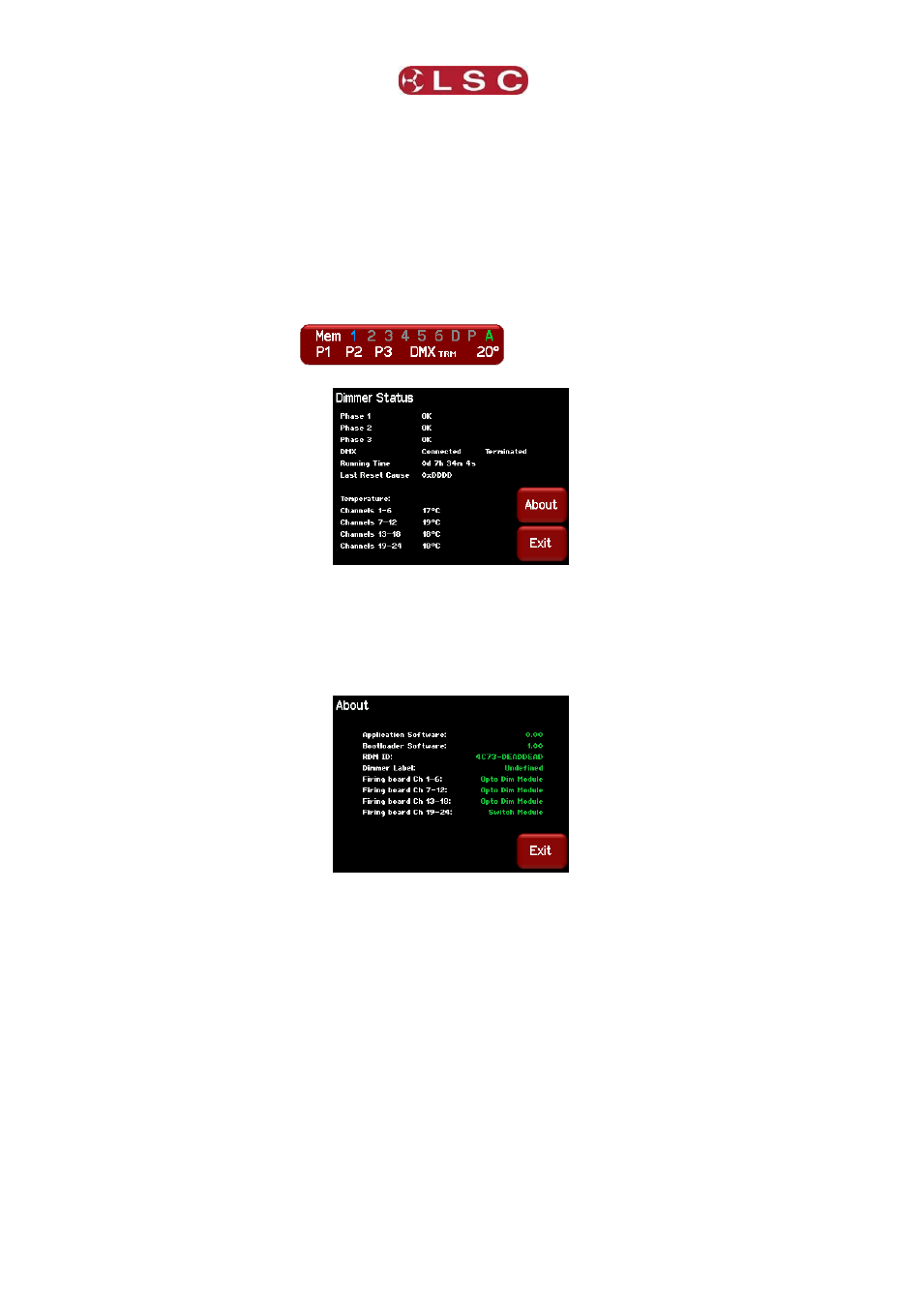
The bottom line indicates:
P1, P2, P3 show the presence of the input power phases.
Flashing Red is not present.
DMX shows the presence of a DMX control signal.
Flashing Red is not present.
TRM indicates that the DMX line is terminated by the internal “DMX TERM” switch.
The internal temperature of the Redback is shown in degrees Celsius.
Pressing the status button
reveals the detailed “Dimmer Status”.
It shows the presence of the input power phases, DMX presence, position of the DMX
termination switch, dimmer running time, last cause of a reset and the individual
temperatures of the internal modules of the Redback.
Pressing [About] shows the software versions and the type of power modules (Firing
boards).
Redbacks are constructed using internal power modules that contain 6 channels each. Two
types of power modules are available:
Dimmer modules.
Switch modules.
Redback’s can be therefore be ordered with combinations of dimming modules and
switching modules to provide a system with dimmed channels for conventional lighting and
non-dimmed (switched) channels for control of devices that require “non-dimmed” power
such as LED fixtures or moving lights.
For example, in the menu above, there are 18 channels of dimming and 6 channels of
switched power.