120vac input power, 3 phase delta input power, Optional control panels – LSC Lighting Redback Wallmount Operators Manual User Manual
Page 8: Wallplates, Panic button, Front panel, Touch screen control panel
Product Description
Redback Wallmount Dimmer
Operator Manual V1.3
Page 4
1.4.6 100-120VAC Input Power
Redback’s can be supplied for 100-120VAC input power operation.
1.4.7 3 Phase Delta Input Power
Redback’s can be supplied wired for 3 phase Delta input power operation.
1.5 OPTIONAL CONTROL PANELS
1.5.1 Wallplates
Wall plates are optional remote control switch plates that can be used to control any of the
6 internal memories that are stored in the Redback. Wall plates are available with either 1,
2 or 6 buttons.
1.5.2 Panic Button
Panic buttons are available to control the “Panic/Evacuation” lighting memory in the
Redback. They use a push button to activate and a key switch to de-activate.
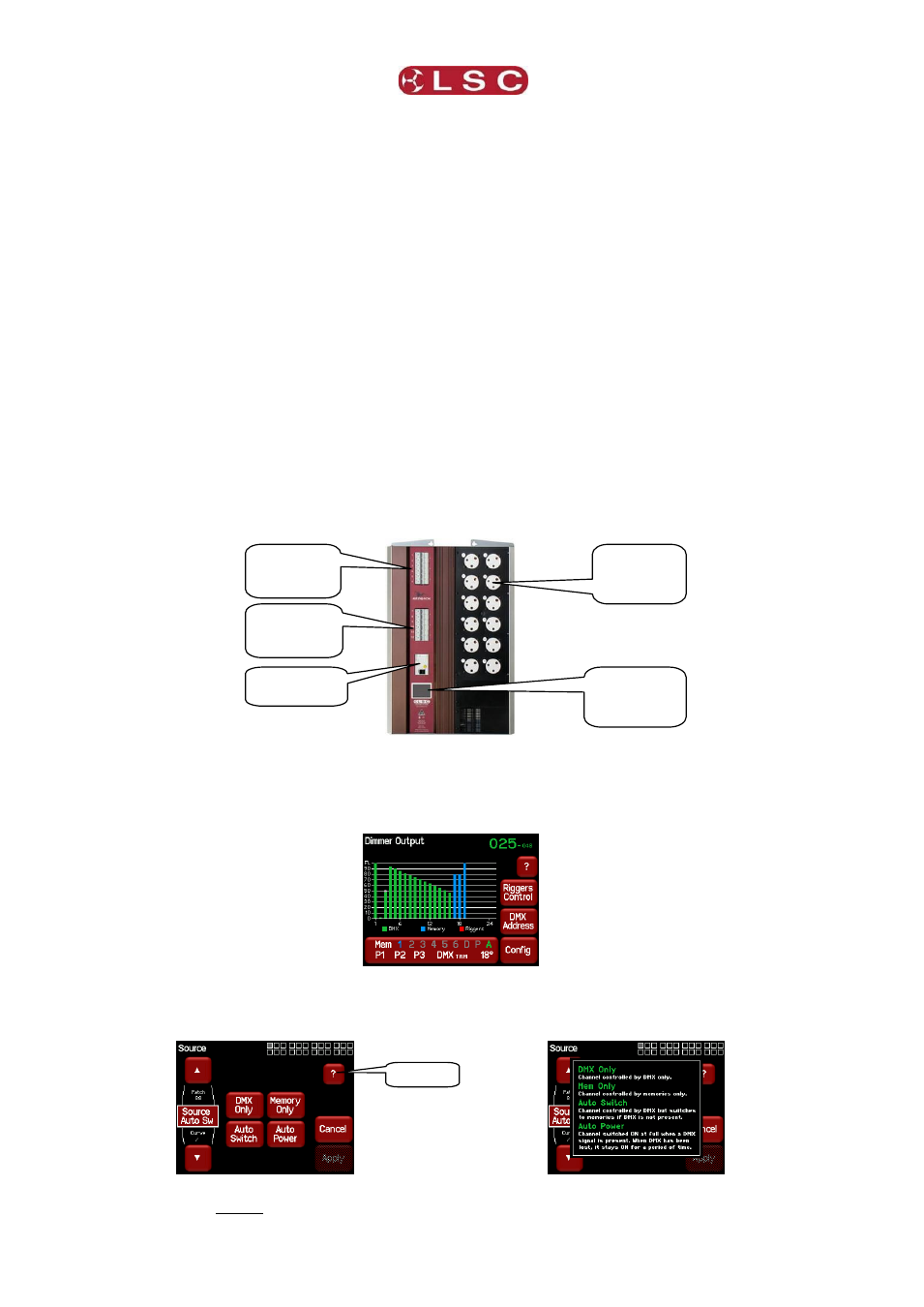
1.6 FRONT PANEL
The front panel contains the input RCD (Residual Current Device) breaker (optional), load
MCB (Miniature Circuit Breakers), and LCD touch screen. Depending upon your model of
Redback, load circuits are either plugged into the output connectors or hard wired to the
internal load connectors.
12 channel Redback fitted with UK output sockets
1.7 TOUCH SCREEN CONTROL PANEL
The Redback Wallmount dimmer uses a colour LCD touch screen which is operated by
touching the virtual buttons and faders with your finger or a stylus.
The “Dimmer Output” home page shows the channel levels.
Many menus have Help screens available. Press the [?] button (when available) to see the
help screen. For example:
Pressing [?] shows……
Press anywhere within the help screen to cancel.
Bank 1
Load Circuit
Breakers
Bank 2
Load Circuit
Breakers
Output
connectors
(optional).
Input RCD
(optional)
LCD Touch
Screen
Control Panel
? Help