H3C Technologies H3C SR6600 User Manual
Page 109
Advertising
99
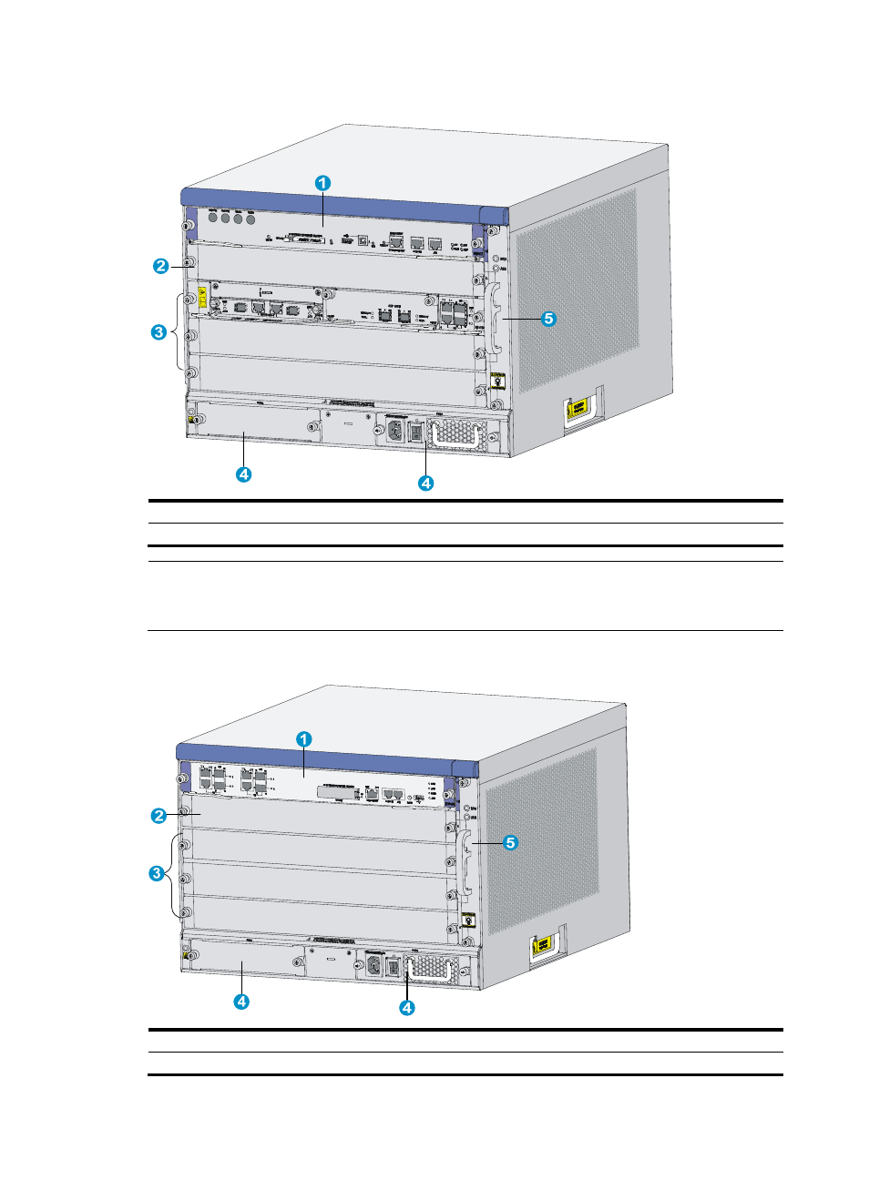
Figure 96 Front view (an RSE-X1 MPU installed)
(1) MPU slot (slot 1)
(2) MPU/service module slot (slot 2)
(3) Service module slot (slot 3 through slot 5)
(4) Power module slots
(5) Fan tray
NOTE:
In this figure, one RSE-X1 MPU is installed. You can install one more RSE-X1 MPU or install one service
module in the MPU/service module slot.
Figure 97 SR6608 front view (an MCP-X1 installed)
(1) MPU slot (slot 1)
(2) MPU/Service module slot (slot 2)
(3) Service module slots (slots 3 through 5)
(4) Power module slots
(5) Fan tray
Advertising
See also other documents in the category H3C Technologies Routers:
- H3C S12500X-AF Series Switches (3 pages)
- H3C S12500X-AF Series Switches (3 pages)
- H3C S12500X-AF Series Switches (53 pages)
- H3C S12500 Series Switches (19 pages)
- H3C MSV 50 (8 pages)
- H3C S12500 Series Switches (21 pages)
- H3C S9500E Series Switches (4 pages)
- H3C S7500E Series Switches (3 pages)
- H3C WA2200 Series WLAN Access Points (42 pages)
- H3C S12500-X Series Switches (8 pages)
- H3C SR6600 (64 pages)
- H3C S9500E Series Switches (36 pages)
- H3C WA3600 Series Access Points (237 pages)
- H3C S9500E Series Switches (270 pages)
- H3C MSR 900 (249 pages)
- H3C S12500 Series Switches (163 pages)
- H3C S12500 Series Switches (170 pages)
- H3C MSR 900 (96 pages)
- H3C MSR 900 (443 pages)
- H3C MSR 900 (468 pages)
- H3C S9500E Series Switches (32 pages)
- H3C S9500E Series Switches (241 pages)
- H3C S12500 Series Switches (39 pages)
- H3C S6800 Series Switches (59 pages)
- H3C LSBM1WCM2A0 Access Controller Module (197 pages)
- H3C S10500 Series Switches (27 pages)
- H3C LSBM1WCM2A0 Access Controller Module (226 pages)
- H3C S6300 Series Switches (188 pages)
- H3C MSR 900 (410 pages)
- H3C MSR 900 (239 pages)
- H3C WA3600 Series Access Points (394 pages)
- H3C S10500 Series Switches (2 pages)
- H3C S10500 Series Switches (2 pages)
- H3C S10500 Series Switches (2 pages)
- H3C S10500 Series Switches (2 pages)
- H3C S10500 Series Switches (2 pages)
- H3C S10500 Series Switches (2 pages)
- H3C S10500 Series Switches (2 pages)
- H3C S10500 Series Switches (1 page)
- H3C S7500E Series Switches (19 pages)
- H3C S7500E Series Switches (115 pages)
- H3C S6300 Series Switches (58 pages)
- H3C S6300 Series Switches (208 pages)
- H3C S6300 Series Switches (251 pages)
- H3C S10500 Series Switches (140 pages)