H3C Technologies H3C SR6600 User Manual
Page 48
38
Some cards on the router provide shielded covers for the fiber ports (such as SFP ports). Before using such
fiber ports, remove the shielded covers. Keep the shielded covers correctly. When the fiber ports are not
in use, install the shielded covers.
Fiber connectors are fitted with dust caps. Keep the dust caps correctly when the fiber connectors are in
use. Install dust caps when the fiber connectors are not in use to avoid damage to their end face. Replace
the dust cap if it is loose or polluted.
Before connecting an optical fiber, use dust free paper and absolute alcohol to clean the end face of the
two fiber connectors. You can brush the end faces only in one direction.
After a fiber is installed well, the bend radius must be not less than 10 cm (3.94 in).
If the fiber has to pass through a metallic board hole, the hole must have a sleek and fully filleted surface
(the filleting radius must be not less than 2 mm, or 0.08 in). When passing through a metallic board hole
or bending along the acute side of mechanical parts, the fiber must wear jackets or cushions.
Insert and remove a plug with care. Never exert a fierce force to the fiber or plug; otherwise the plug
might be damaged or the fiber might be broken. Never pull, press or extrude the fiber fiercely. For the
allowed maximum tensile load and crush load, see
.
Table 9 Characteristics of single-mode and multi-mode optical fibers
Item Single-mode fiber
Multi-mode fiber
Core
Small core (10 micrometers or less)
Larger core than single-mode fiber (50
micrometers, 62.5 micrometers or greater)
Dispersion Less
dispersion
Allows greater dispersion and therefore, signal
loss exists.
Light source and
transmission
distance
Users lasers as the light source often
within campus backbones for
distance of several thousand meters
Uses LEDs as the light source often within LANs
or distances of a couple hundred meters within a
campus network
Table 10 Allowed maximum tensile force and crush load
Period of force
Tensile load (N)
Crush load (N/mm)
Short period
150
500
Long term
80
100
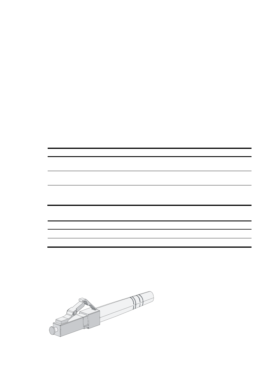
Fiber connectors are indispensable passive components in an optical fiber communication system. They
allow the removable connection between optical channels, which makes the optical system debugging
and maintenance more convenient. There are multiple types of fiber connectors.
shows an LC
connector.
Figure 41 Appearance of an LC connector