Yx z, Yx z dr– dr – HEIDENHAIN TNC 407 (280 580) User Manual User Manual
Page 118
5-19
TNC 425/TNC 415 B/TNC 407
5
Programming Tool Movements
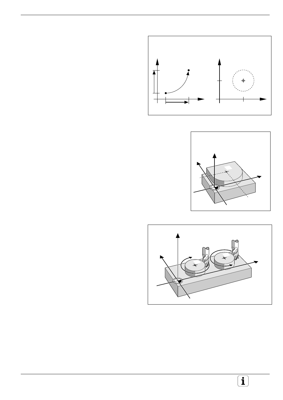
Fig. 5.22:
Circular arc and circle center
Fig. 5.23:
Circle center coordinates
Fig. 5.24:
Direction of rotation for circular movements
Path Contours - Cartesian Coordinates
Y
X
Y
X
Y
CC
CC
X
CC
Y
X
Z
Y
CC
CC
X
CC
CC
CC
Y
X
Z
DR–
DR+
Circles and circular arcs
The TNC moves two machines axes simultaneous-
ly in a circular path relative to the workpiece. This
is also possible in secondary axes U, V, and W.
Circle Center CC
You can define a circle by entering its center CC.
A circle center also serves as reference (pole) for
polar coordinates.
Direction of Rotation DR
When there is no tangential transition to another
contour element, enter the mathematical direction
of rotation DR:
• A clockwise direction of rotation is mathemati-
cally negative: DR-
• A counterclockwise direction of rotation is
mathematically positive: DR+