HEIDENHAIN TNC 407 (280 580) User Manual User Manual
Page 301
TNC 425/TNC 415 B/TNC 407
9-34
9
3D Touch Probe Systems
.
.
.
e.g.
0
ENT
5
e.g.
0
ENT
5
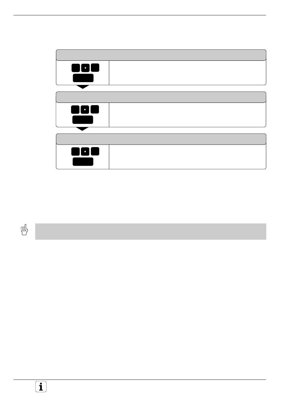
Resulting NC blocks:
TCH PROBE
17.0 CONTOUR LINES
TCH PROBE
17.1 TIME: 0 X+0 Y+0
TCH PROBE
17.2 ORDER: Y– / X–
TCH PROBE
17.3 F1000
MIN.L.SPAC: 0.2 L.SPAC: 0.5
PP.INT: 0.5 TOL: 0.1
e.g.
0
ENT
1
Digitizing with a Measuring Touch Probe
LINE SPACING AND DIRECTION ?
Enter the maximum line spacing, for example +0.5 mm. The alge-
braic sign determines the direction in which the probe moves to start
the next contour line.
MAX. PROBE POINT INTERVAL ?
Enter the maximum probe point interval, for example 0.5 mm.
TOLERANCE ?
Enter the diameter of the tubular tolerance zone, for example
0.1 mm.
Before cycle 17: CONTOUR LINES, the program must have a range defined in cycle 5: RANGE or cycle 15: RANGE
(TABLE).