HEIDENHAIN TNC 407 (280 580) User Manual User Manual
Page 331
10-5
10
External Data Transfer
TNC 425/TNC 415 B/TNC407
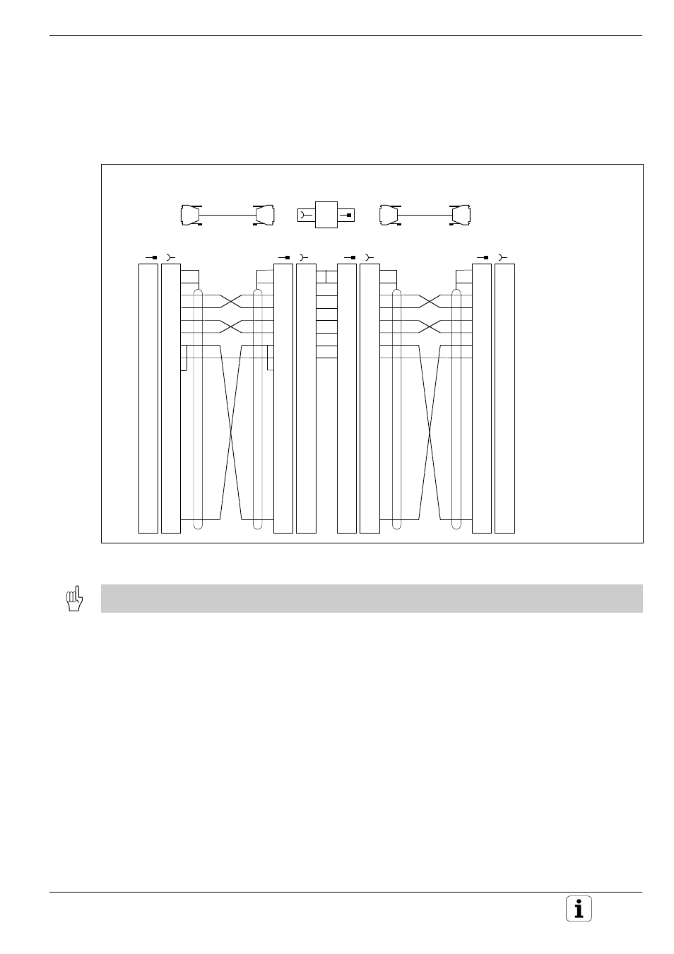
Fig. 10.2:
Pin layout of the RS-232-C/V.24 interface for HEIDENHAIN devices
GND Chassis
RXD Receive data
TXD Transmit data
CTS Clear to send
RTS Request to send
DTR Data terminal ready
GND Signal ground
DSR Data set ready
1
2
3
4
5
6
7
8
9
10
11
12
13
14
15
16
17
18
19
20
1
2
3
4
5
6
7
8
9
10
11
12
13
14
15
16
17
18
19
20
•
•
X21 Data interface RS-232-C/V.24
Id.-Nr. 239 760..
max. 17 m
1
2
3
4
5
6
7
8
9
10
11
12
13
14
15
16
17
18
19
20
YL
GN
PK
GY
BN
RD
BL
1
2
3
4
5
6
7
8
9
10
11
12
13
14
15
16
17
18
19
20
1
2
3
4
5
6
7
8
9
10
11
12
13
14
15
16
17
18
19
20
1
2
3
4
5
6
7
8
9
10
11
12
13
14
15
16
17
18
19
20
•
•
1
2
3
4
5
6
7
8
9
10
11
12
13
14
15
16
17
18
19
20
GN
YL
GY
PK
BL
RD
BN
1
2
3
4
5
6
7
8
9
10
11
12
13
14
15
16
17
18
19
20
•
•
WH/BN
GND
TXD
RXD
RTS
CTS
DSR
GND
DTR
Id.-Nr. 274 545 01
3 m
RS-232-C Adapter Block
Id.-Nr. 239 758 01
Peripheral
unit
•
•
•
•
•
•
•
WH/BN
WH/BN
WH/BN
10.3 Pin Layout and Connecting Cable for the Data Interfaces
RS-232-C/V.24 Interface
HEIDENHAIN devices
The connector pin layout on the adapter block differs from that on the TNC logic unit (X21).