Tch probe 5.0 range, Yx z – HEIDENHAIN TNC 407 (280 580) User Manual User Manual
Page 308
9-41
TNC 425/TNC 415 B/TNC 407
9
3D Touch Probe Systems
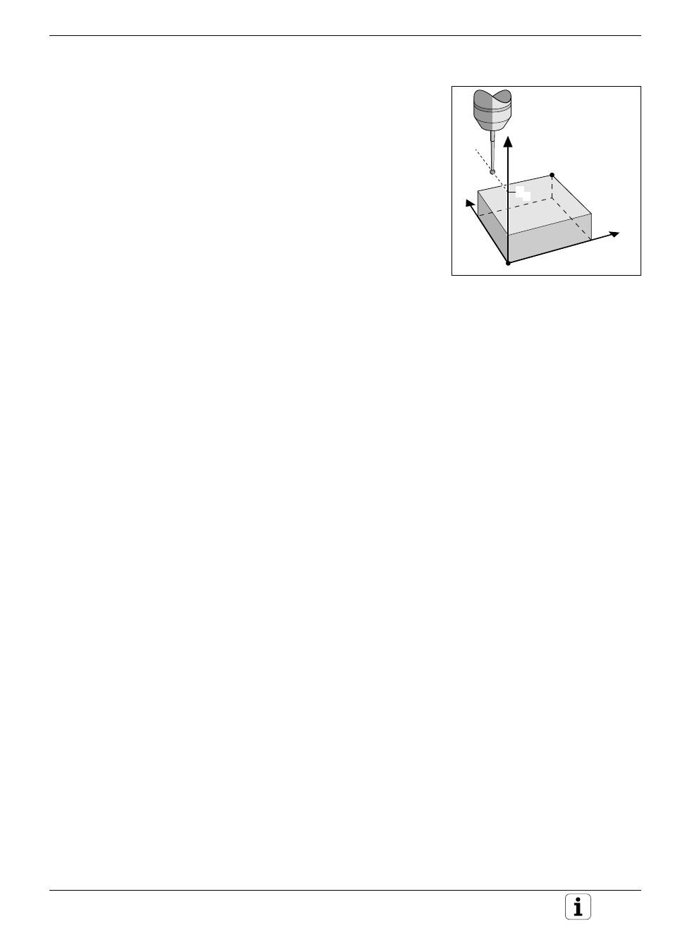
Fig. 9.28:
Clearance height and digitizing
range
Digitizing with the TS 120 Touch Probe
Y
X
Z
MAX
MIN
S
Z
Defining the digitizing range
The digitizing range is defined in cycle 5 RANGE. The model to be
scanned must lie within this range. The range is programmed – similar to
defining the workpiece blank – by entering the MIN and MAX point
coordinates of the three main axes X, Y and Z.
Input
• PGM NAME DIGITIZING DATA?
Name of the file in which the digitized data is to be stored
• TCH PROBE AXIS ?
Enter the touch probe axis
• MIN. POINT RANGE
Lowest coordinates in the range to be digitized
• MAX. POINT RANGE
Highest coordinates in the range to be digitized
• CLEARANCE HEIGHT
Position in the probe axis at which the stylus cannot collide with the
model