Write multiple registers normal response message, Write multiple registers fault response message – Yaskawa F7 Modbus User Manual
Page 26
Message Formats 2-9
►
Write Multiple Registers Normal Response Message
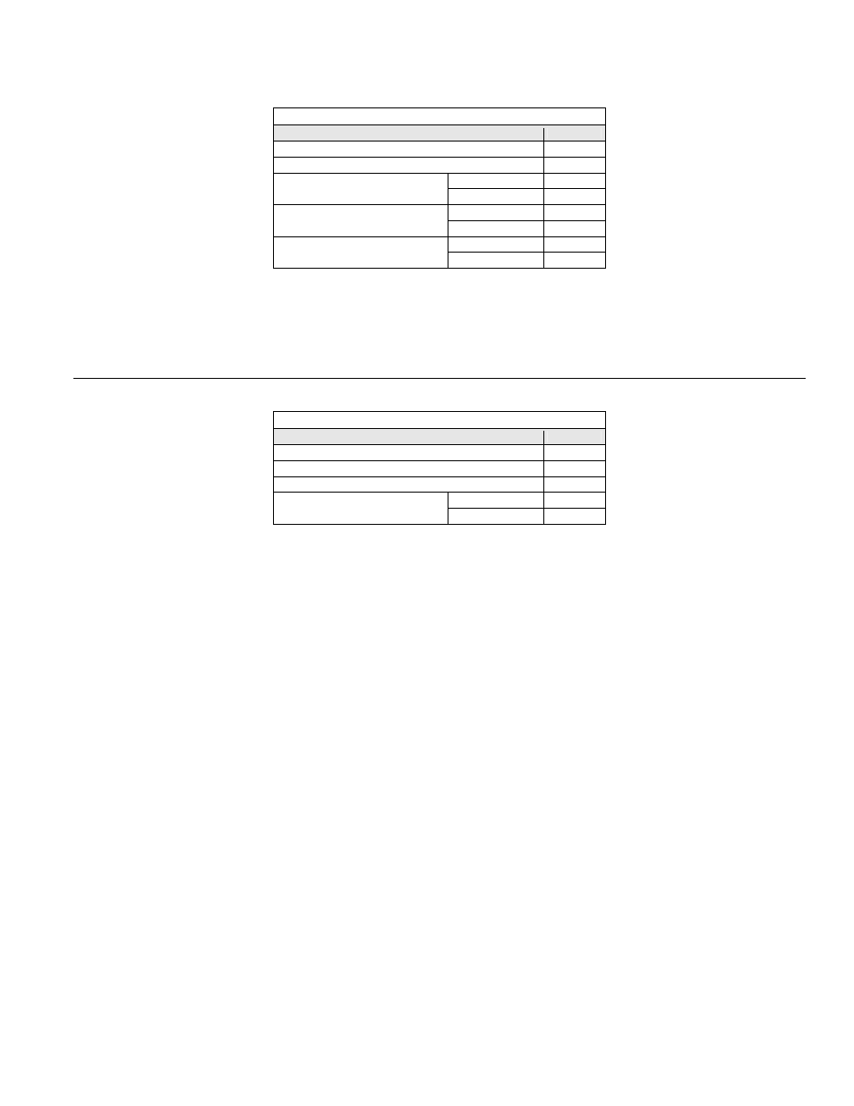
Table 2.12 - Write Registers Normal Response Message
Description
Data
Slave Address
01h
Function Code
10h
Upper
00h
Starting Register
Lower
01h
Upper
00h
Quantity
Lower
02h
Upper
10h
CRC-16
Lower
08h
The normal response message contains the same slave address, function code, starting register and quantity as the command message, indicating
to the master which slave is responding and to what type of function it is responding.
The starting register is the address of the first register written. In the response message above the starting register address is 01h (0001h).
The quantity indicates how many consecutive registers were written. In this case the quantity is 2.
►
Write Multiple Registers Fault Response Message
Table 2.13 - Write Registers Fault Response Message
Description
Data
Slave Address
01h
Function Code
90h
Error Code
02h
Upper
CDh
CRC-16
Lower
C1h
The fault response message contains the same slave address as the command message, indicating to the master which slave is responding.
The function code of a fault response message is the logical OR of 80h and the original function code of 10h. This indicates to the master that the
message is a fault response message, instead of a normal response message.
The error code indicates where the error occurred in the command message. The value of 02h in the error code field of this fault response
message indicates that the command message requested data to be written to an invalid register. Refer to the section Error Codes, Table 2-14, for
more information on returned error codes.