Command registers (read / write), Command registers (read / write) -1, F7u parameters 4-1 – Yaskawa F7 Modbus User Manual
Page 40
F7U Parameters 4-1
Command Registers (Read / Write)
Command registers are those registers used to control the operation of the F7 drive either through a network interface (option card) or via
serial communications. These registers are available during an active Run command. It should be noted that serially commanded multi-
function inputs are logically OR’d with their external input terminal counterpart.
The “Addr” column contains the register address in hexadecimal format. F7 drive registers are always referred to in hexadecimal format.
The “Function” column contains the register name. The “Bit” and “Description” columns contain the list of available bits for that register
and a short description of each. If the “Bit” column is empty, the register contains word data and individual bits are meaningless.
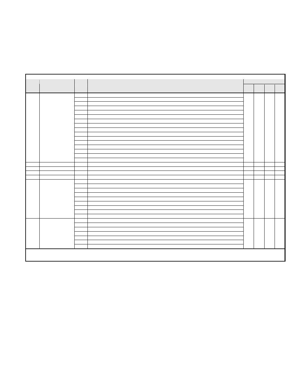
Table 4.1 – Command Registers (Read / Write)
Mode
Addr
Function
Bit
Description
V/f
V/f
wPG
OLV FV
0h
0 = Stop 1 = Run
1h
0 = Forward 1 = Reverse
2h External
Fault
3h Fault
reset
4h
ComNet (0 = b1-01 = pre-selected source -- 1 = b1-01 = 3 (serial communications))
5h
ComCtrl (0 = b1-02 = pre-selected source -- 1 = b1-02 = 3 (serial communications))
6h
Multi-Function Input 1 @ S3 Function set by setting of H1-01
7h
Multi-Function Input 2 @ S4 Function set by setting of H1-02
8h
Multi-Function Input 3 @ S5 Function set by setting of H1-03
9h
Multi-Function Input 4 @ S6 Function set by setting of H1-04
Ah
Multi-Function Input 5 @ S7 Function set by setting of H1-05
Bh
Multi-Function Input 6 @ S8 Function set by setting of H1-06
Ch Reserved
Dh Reserved
Eh Reserved
0001h Command
Fh Reserved
0002h Frequency Reference
Dependent on setting of o3-02
0006h PID Setpoint
PID Setpoint
0007h Analog Output 1 Setting
(-11 ~ 11)/726 VDC
0008h Analog Output 2 Setting
(-11 ~ 11)/726 VDC
0h
Multi-Function Output 1
1h
Multi-Function Output 2
2h
Multi-Function Output 3
3h Reserved
4h Reserved
5h Reserved
6h
Fault Relay Output
7h
Fault Relay N.C.
0009h Outputs
8h-Fh Reserved
0h Reserved
1h
PID Value 0006h is used
2h–Bh Reserved
Ch
Simultaneous Broadcast Data Terminal S5 Enable*
Dh
Simultaneous Broadcast Data Terminal S6 Enable*
Eh
Simultaneous Broadcast Data Terminal S7 Enable*
000Fh Command
Selection
Fh
Simultaneous Broadcast Data Terminal S8 Enable*
Note: *
These bits must be set in order to use the Simultaneous Broadcast Register multi-function inputs 3, 4, 5 and 6 (bits 0Ch, 0Dh, 0Eh and 0Fh respectively).
Refer to Table 4.3 - Simultaneous Broadcast Registers (Write only).