2 three-phase 400 v, M-ii, Outline – Yaskawa Sigma-5 Large Capacity Users Manual: Design and Maintenance-Command Option Interface User Manual
Page 33: 6 servopack and converter internal block diagrams
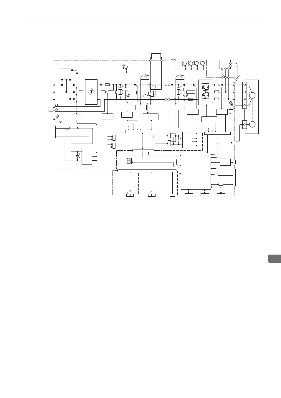
1.6 SERVOPACK and Converter Internal Block Diagrams
1-11
1
Outline
1.6.2 Three-phase 400 V
∗ This external input signal is used by the option module.
For details, refer to the manual of the connected option module.
Control
power
supply
L1
+
B2
L2
+24 V
0 V
U
V
W
+5 V
Voltage sensor
gate drive
- 1
Voltage
sensor
Fan
2
L3
MC drive
Voltage
sensor
- 2
CHARGE
P24 V
Fan
1
SPD
+15 V
+24 V×2
P
N
+24 V
24C
+24 V
24C
CN103
CN104
CN901
Fan
Temperature
sensor
P
N
CHARGE
Voltage
sensor
Current
sensor
Gate drive
Fan
4
Fan 3
(for 55-kW
models only)
Temperature
sensor
Converter I/O
SERVOPACK
control power supply
Servomotor
ENC
M
CN103
CN104
P24 V
0 V
CN901
Control
power
supply
+24 V×6
24 V
+5 V
±15 V
ASIC
(PWM control, etc.)
CPU
(Position and speed
calculation, etc.)
CN2
Panel display
CN21
*
CN22
*
CN31
*
Feedback module
Safety module
Command option
module
P24 V P24 V P24 V
24 V
-
B1
DU
DV
DW
CN115
Dynamic
brake
unit
PC
I/O signals
CN5
CN3
Digital
operator
CN7
CN8
Safety function
signals
CN1
Analog
voltage
converter
Analog monitor output
Encoder pulse output
I/O
Control power supply
Main circuit
power supply
The 24-VDC power
supply is not included.
(
)
Regenerative
resistor unit
M-II