Input buffer reference voltage (vref) – Altera PHYLite User Manual
Page 12
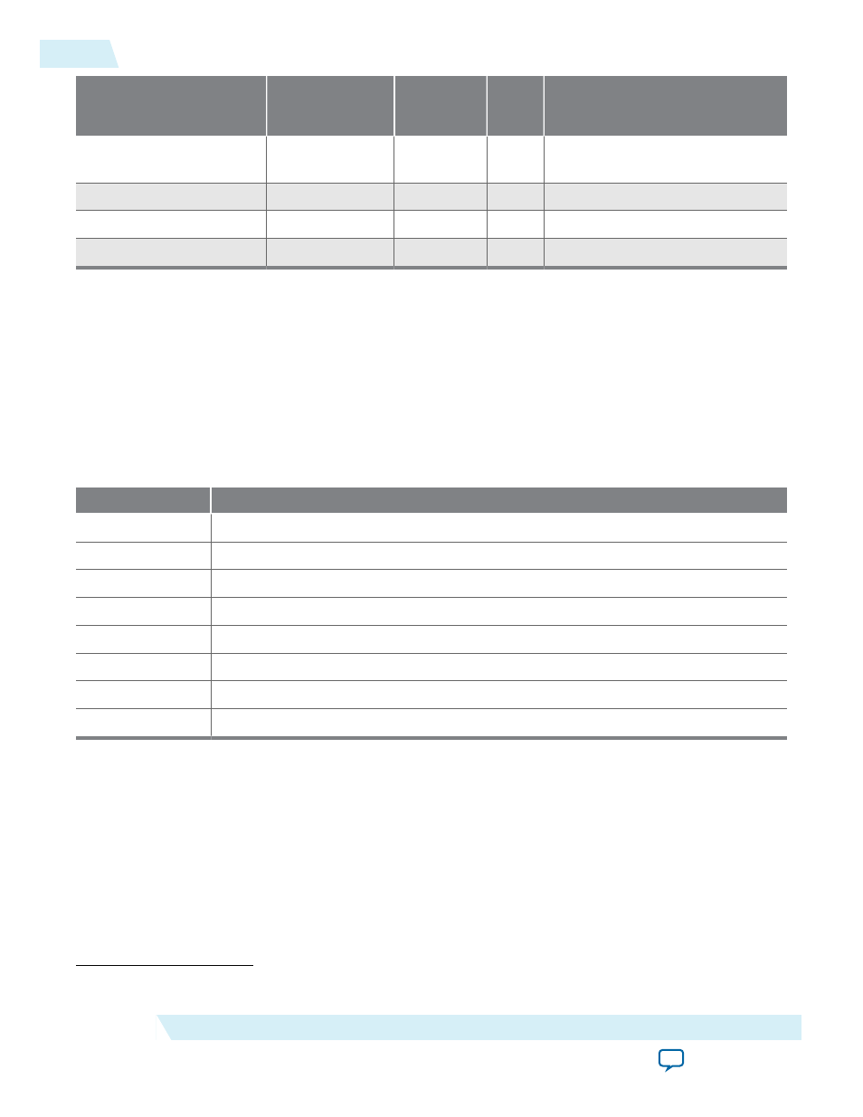
I/O Standard
Valid Input
Terminations (Ω)
(1)
Valid Output
Terminations
(Ω)
(1)
RZQ
(Ω)
Differential/Complementary I/O
Support
1.2-V POD
34, 40, 48, 60, 80,
120, 240
34, 40, 48, 60
240
Yes
1.2-V
—
—
—
No
1.5-V
—
—
—
No
1.8-V
—
—
—
No
Input Buffer Reference Voltage (VREF)
The 1.2-V POD I/O standard allows a configurable VREF. By default, the externally provided VREF is
used and using an internal VREF requires the following .qsf assignments:
set_instance_assignment -name VREF_MODE <mode> -to <pin_name>
Note: The VREF settings are at the lane level, so all pins using a lane must have the same VREF settings
(including GPIOs).
Table 6: VREF_MODE Description
VREF Mode
Description
EXTERNAL
Use the external VREF. This is the default.
CALIBRATED Use internal VREF generated using VREF codes from the Avalon reconfiguration bus.
VCCIO_45
Use internal VREF generated using static VREF code. VREF is 45% of VCCN
VCCIO_50
Use internal VREF generated using static VREF code. VREF is 50% of VCCN
VCCIO_55
Use internal VREF generated using static VREF code. VREF is 55% of VCCN
VCCIO_65
Use internal VREF generated using static VREF code. VREF is 65% of VCCN
VCCIO_70
Use internal VREF generated using static VREF code. VREF is 70% of VCCN
VCCIO_75
Use internal VREF generated using static VREF code. VREF is 75% of VCCN
(1)
0 is equivalent to none.
12
Input Buffer Reference Voltage (VREF)
ug_altera_phylite
2015.01.16
Altera Corporation
Altera PHYLite for Parallel Interfaces IP Core User Guide