Altera PHYLite User Manual
Page 34
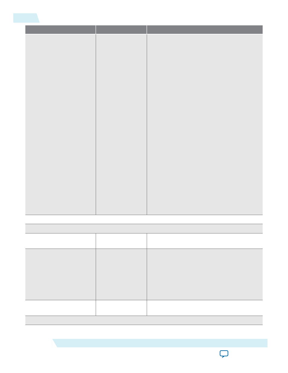
GUI Name
Values
Description
I/O standard
SSTL-12
SSTL-125
SSTL-135
SSTL-15
SSTL-15 Class I
SSTL-15 Class II
SSTL-18 Class I
SSTL-18 Class II
1.2-V-HSTL Class I
1.2-V-HSTL Class II
1.5-V-HSTL Class I
1.5-V-HSTL Class II
1.8-V-HSTL Class I
1.8-V-HSTL Class II
1.2-V POD
1.2-V
1.5-V
1.8-V
None
Specifies the I/O standard of the interface's strobe
and data pins written to the .qip of the IP instance.
When you choose None, the I/O standard is
unspecified in the generated IP.
Group <x> - these parameters are set on a per group basis
Group <x> Pin Settings
Pin type
Input, Output,
Bidirectional
Direction of data pins. This value is set to Bidirec‐
tional by default.
Pin width
1 to 48
Number of pins in this data/strobe group. The
value is set to 9 by default.
A data width of 48 is only achievable if no strobe is
used in the group. The number of strobes is
controlled by the Use output strobe, Strobe
configuration and Use separate capture strobe
parameters.
DDR/SDR
DDR, SDR
Double/single data rate. The value is set to DDR by
default.
Group <x> Input Path Settings
34
Parameter Settings
ug_altera_phylite
2015.01.16
Altera Corporation
Altera PHYLite for Parallel Interfaces IP Core User Guide