Interface, Output path, Figure 4 – Altera PHYLite User Manual
Page 5: For the clock domain boundaries
Interface
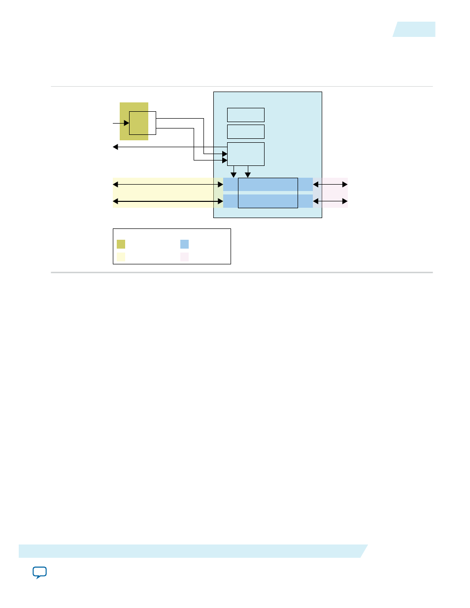
Figure 4: Top-Level Interface
This figure shows the top-level diagram of the Altera PHYLite for Parallel Interfaces IP core interface.
PLL
I/O Lane
I/O Lane
Tile Control
I/O Lane
I/O Lane
VCO/Interpolator
phy_clk
phy_clk_phs
core_clk_out
data_in/out/io
data_in/out/io
Data to/from Core
Group
ref_clk
Reference Clock
Core Clock
PHY Clock
ExternalClock
Legend
The Altera PHYLite for Parallel Interfaces IP core consists of the following interfaces:
• Clocks and Reset
• Core Data and Control (broken down into input and output paths)
• I/O (broken down into input and output paths)
• Avalon Configuration Bus
Related Information
•
For more information about the output path
•
For more information about the input path
•
For more information about core data, control, and I/O interfaces signals
Output Path
The output path consists of a FIFO and an interpolator.
ug_altera_phylite
2015.01.16
Interface
5
Altera PHYLite for Parallel Interfaces IP Core User Guide
Altera Corporation