Strobes – Altera PHYLite User Manual
Page 28
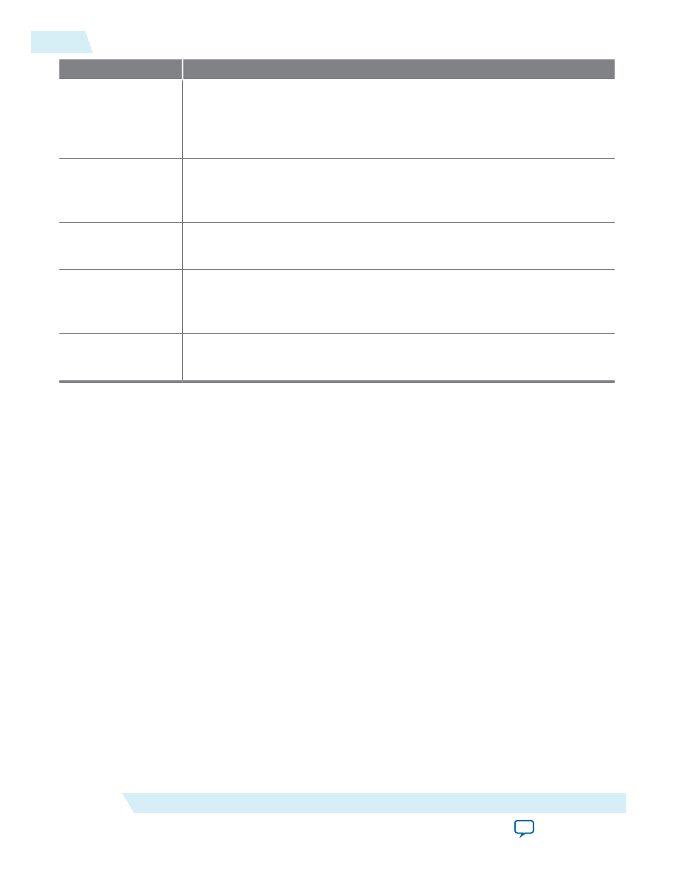
Description
2
Retrieve number of groups in the interface (cache once per interface)
• {id[3:0],24'h00E000} + {4'h0,pt_ptr[23:0]} + 4'h4
• You can skip this if it saved in the core during compilation (for example, hard
coded in RTL logic)
3
Retrieve group information (cache once per group)
• {id[3:0],24'h00E000} + {4'h0,pt_ptr[23:0]} + 24'h4 + grp_num
• Not always necessary
4
Retrieve Lane/Pin Address Offsets for group (cache once per group)
• {id[3:0],24'h00E000} + pt_ptr + {22'd0,num_grps[7:2],2'b00} + 28'd8
5
Perform lane/pin address translation (cache once per pin)
• {id[3:0],24'h00E000} + {12'h000,lane_ptr[15:0]} + lane_num
• {id[3:0],24'h00E000} + {12'h000,pin_ptr[15:0]} + {17'h0,pin_num[5:0], 1'b0}
6
Read/Write Avalon Calibration Bus
• {id[3:0],24'h800000} + read_from_step_4 + intra_lane_addr
Caching look-ups 1-4 (8-bytes of information) allows for pin and lane translations in one look-up.
Strobes
The first pins listed in the pin address look-up table are the strobes. They are also identified by
bits[7:4]
= 0xE
. For separate strobes, the input strobe is always first. For differential and complementary strobes,
the positive pin is the lower index.
Note: The output phase of differential strobes can be modified by writing to either the positive or
negative pin. Only one write is necessary. This is also the case for output only complementary
strobes.
28
Strobes
ug_altera_phylite
2015.01.16
Altera Corporation
Altera PHYLite for Parallel Interfaces IP Core User Guide