Output path signals – Altera PHYLite User Manual
Page 38
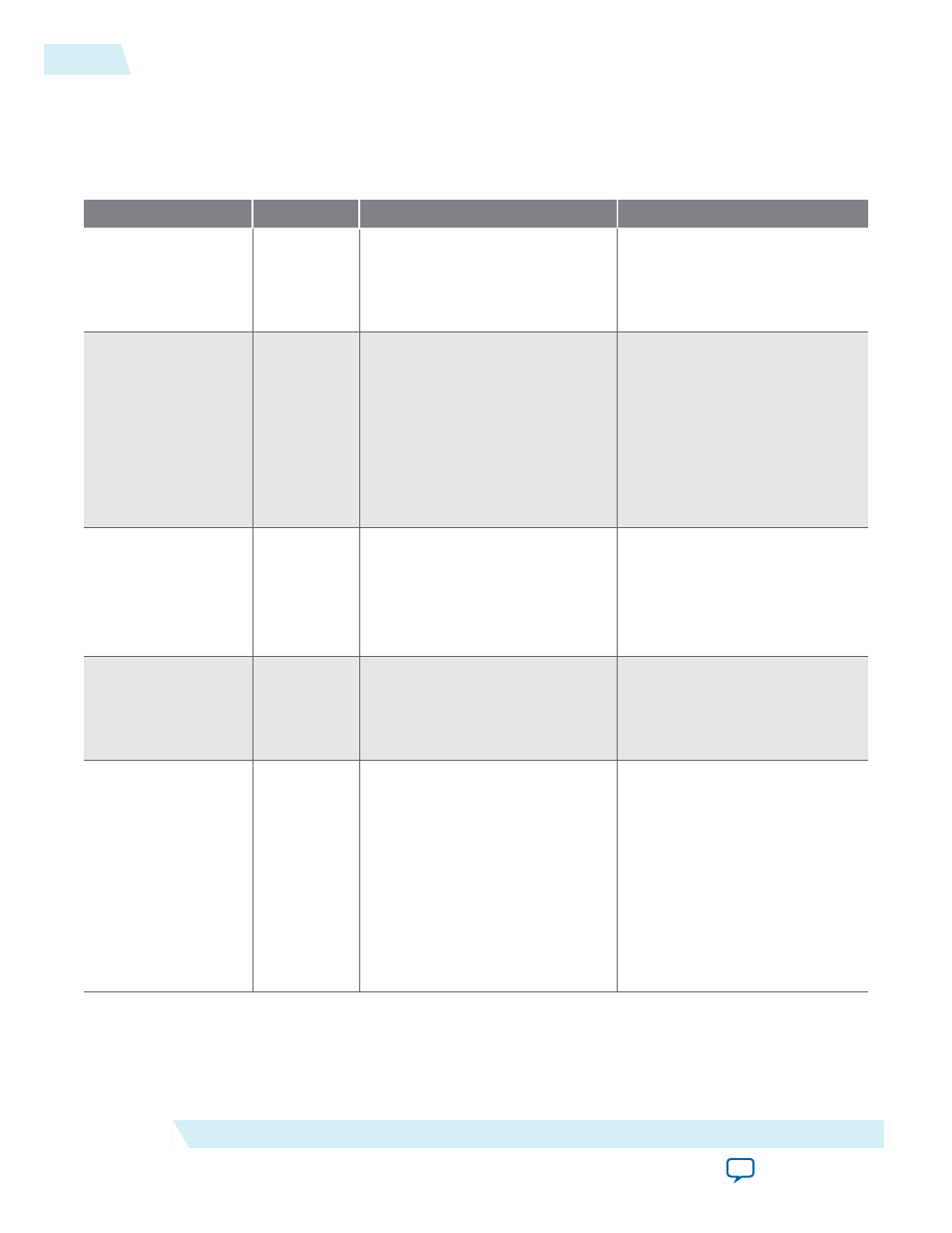
Output Path Signals
Table 19: Output Path Signals
Output path signals are signals that are available when you set the Pin Type parameter to either Output or
Bidirectional.
Signal Name
Direction
Width
Description
oe_from_core
Input
Quarter-rate: 4 x
PIN_WIDTH
Half-rate: 2 x
PIN_WIDTH
Full-rate: 1 x
PIN_WIDTH
Core rate data enable to be
output. Synchronous to the
core_clk
output from the IP
core.
data_from_core
Input
Quarter rate-DDR: 8 x
PIN_WIDTH
Half-rate DDR: 4 x
PIN_WIDTH
Full-rate DDR: 2 x
PIN_WIDTH
Quarter-rate SDR: 4 x
PIN_WIDTH
Half-rate SDR: 2 x
PIN_WIDTH
Full-rate SDR: 1 x
PIN_WIDTH
Core rate data to be output.
Synchronous to the
core_clk
output from the IP core.
strobe_out_in
Input
Quarter-rate: 8
Half-rate: 4
Full-rate: 2
Strobe pattern to be output.
Synchronous to the
core_clk
output from the IP core.
Note: This path is always
DDR.
strobe_out_en
Input
Quarter-rate: 4
Half-rate: 2
Full-rate: 1
Enable output strobe. Synchro‐
nous to the
core_clk
output
from the IP core.
data_out/data_io
Output/
Bidirectional
•
1 to 48 if data configuration is
Single Ended
•
1 to 24 if data configuration is
Differential
Data output to pin. Synchro‐
nous to the
strobe_out
or
strobe_io
output from the IP
core.
If the Pin Type parameter is set
to Output, the
data_out
signals are used. If the Pin
Type parameter is set to
Bidirectional, the
data_io
signals are used.
38
Output Path Signals
ug_altera_phylite
2015.01.16
Altera Corporation
Altera PHYLite for Parallel Interfaces IP Core User Guide