Start-up sequence following reset, Start-up sequence following reset -6 – Altera CPRI v6.0 MegaCore Function User Manual
Page 36
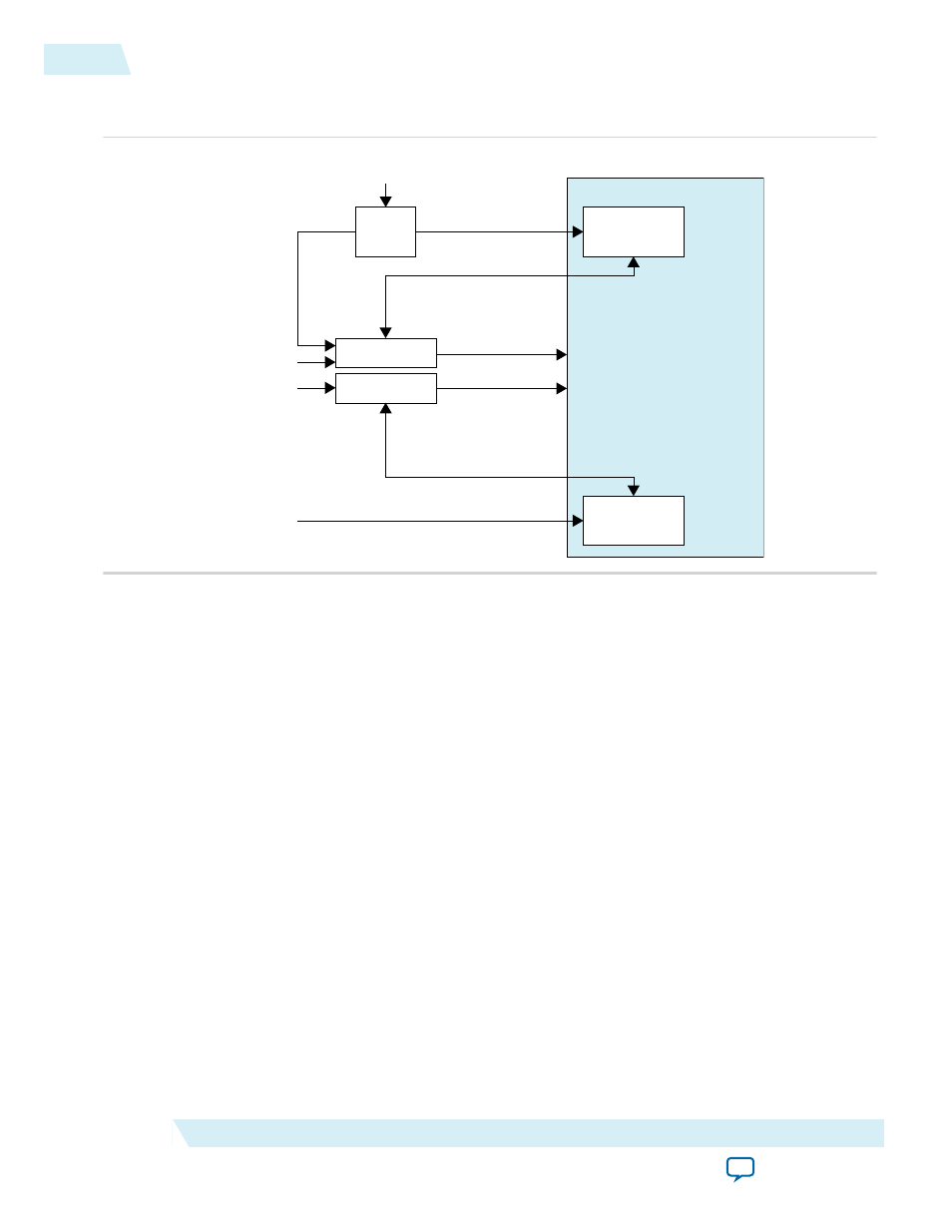
Figure 3-3: Required External Blocks
An example showing how you could connect required components to a single CPRI v6.0 IP core.
Reset Controller
Reset Controller
TX
PLL
Transmitter
(Native PHY)
Receiver
(Native PHY)
User-Defined
Reference Clock
xcvr_ext_pll_clk
xcvr_tx_analogreset
xcvr_tx_digitalreset
xcvr_tx_cal_busy
xcvr_rx_analogreset
xcvr_rx_digitalreset
xcvr_rx_is_lockedtodata
xcvr_rx_cal_busy
xcvr_cdr_refclk
reset_tx
reset_rx
pll_locked
CPRI v6.0 IP Core
xcvr_reset_tx_ready
xcvr_reset_rx_ready
To reset the CPRI v6.0 IP core, you must trigger the reset controller logic by asserting the active low
reset_tx
and
reset_rx
input signals. When you trigger the reset controllers, they should deassert the
xcvr_reset_tx_ready
and
xcvr_reset_rx_ready
input ready signals to the IP core. After each reset
controller completes resetting the transceiver and IP core data path, it should assert the relevant ready
signal.
Related Information
Integrating Your IP Core in Your Design: Required External Blocks
Shows main data path reset signals and how the reset controller connects to the IP core.
Start-Up Sequence Following Reset
After reset, if you turned on Enable start-up sequence state machine in the CPRI v6.0 IP core, the
internal state machine performs link synchronization and other initialization tasks. If you did not turn on
Enable start-up sequence state machine, user logic must perform these functions.
3-6
Start-Up Sequence Following Reset
UG-01156
2014.08.18
Altera Corporation
Functional Description