Aux interface synchronization, Auxiliary latency cycles, Aux interface synchronization -17 – Altera CPRI v6.0 MegaCore Function User Manual
Page 47: Auxiliary latency cycles -17
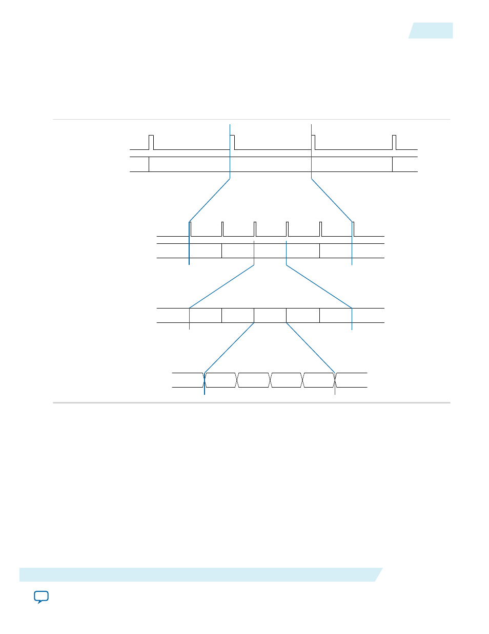
AUX Interface Synchronization
Figure 3-10: Relationship Between Synchronization Pulses and Numbers on the AUX Interface
The output synchronization signals are useful for custom user logic, including frame synchronization
across hops in multi-hop configurations.
The output synchronization signals are derived from the CPRI frame synchronization state machine.
aux_{rx,tx}_rfp
aux_{rx,tx}_bfn
aux_{rx,tx}_hfp
aux_{rx,tx}_z
aux_{rx,tx}_x
aux_{rx,tx}_seq
0
1
...
NUM_SEQ - 1
2
...
...
2
1
0
255
149
1
0
n
n + 1
n + 2
Hyperframe
Radio Frame (10 ms)
Basic Frame
Related Information
on page 3-10
Describes the AUX interface signals and provides AUX interface timing diagrams.
Auxiliary Latency Cycles
Altera provides configurable write latency on the AUX TX interface and other direct TX interfaces to
support user logic with sufficient advance notice of the position in the CPRI frame. The processing time
that user logic requires after determining the current position in the CPRI frame is implementation
specific, and the default write latency of a single
cpri_clkout
cycle might not be adequate. Using the
Auxiliary latency cycle(s) parameter, you can set the write latency to the number of clock cycles required
for your system to process data before sending it on the AUX TX interface or other direct TX interface.
UG-01156
2014.08.18
AUX Interface Synchronization
3-17
Functional Description
Altera Corporation