Altera CPRI v6.0 MegaCore Function User Manual
Page 46
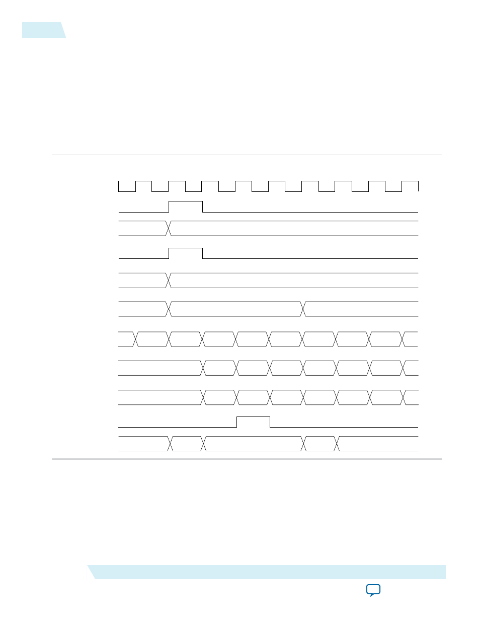
Figure 3-9: AUX TX Timing Diagram with Error
Illustrates the behavior of the
aux_tx_err
signal on the AUX TX interface of a CPRI v6.0 IP core running
at 0.6144 Gbps. The
aux_tx_ctrl
signal shows that when
aux_tx_seq
has the value of zero, the first byte
at the corresponding position in the target CPRI frame is a control byte. The value of the Auxiliary latency
cycle(s) parameter is zero. Therefore, the data on
aux_tx_data
is delayed by one clock cycle from the
value on
aux_tx_seq
. The data that appears on
aux_tx_data
when
aux_tx_seq
has the value of 1 is the
data that targets position X.Y.Z.0 in the target CPRI frame.
The value of Mask #1 is presumably 0xFFXXXXXX, indicating that the incoming data on
aux_tx_data
is
intended to overwrite this control byte in the target CPRI frame. Therefore, in the following
cpri_clkout
cycle, the IP core asserts the
aux_tx_err
signal.
4095
0
0
3
255
1
149
0
2
0
1
2
3
0
1
2
X
Data #1
Data #2
Data #3
Data #4
Data #5
cpri_clkout
aux_tx_rfp
aux_tx_bfn
aux_tx_hfp
aux_tx_hfn
aux_tx_x
aux_tx_seq
aux_tx_data
aux_tx_mask
Auxiliary latency cycle(s) == 0
Data #6
X
Mask #1
Mask #2
Mask #3
Mask #4
Mask #5
Mask #6
0000
1000
0000
1000
0000
aux_tx_err
aux_tx_ctrl[3:0]
Related Information
•
on page 3-17
Illustrates the relationship between the AUX synchronization signals.
•
The Auxiliary latency cycle(s) parameter affects the relative timing of the data on the aux_tx_data and
aux_tx_mask busses. This section provides an explanation of the parameter's effect and purpose.
3-16
AUX Interface Signals
UG-01156
2014.08.18
Altera Corporation
Functional Description