Altera CPRI v6.0 MegaCore Function User Manual
Page 87
Clock Name
Direction
Description
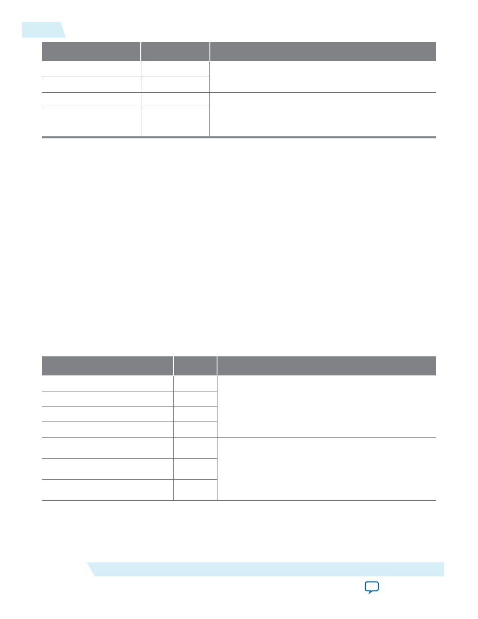
ex_delay_clk
Input
Extended delay measurement interface
ex_delay_reset
Input
rx_lcv
Output
L1 debug interface
These signals are available only if you turn on Enable debug
interface in the CPRI v6.0 parameter editor.
rx_freq_alarm
Output
Related Information
•
CPRI v6.0 IP Core Clocking Structure
on page 3-3
•
CPRI v6.0 IP Core Reset Requirements
•
CPU Interface to CPRI v6.0 IP Core Registers
•
on page 3-36
•
Start-Up Sequence Following Reset
•
on page 3-40
•
on page 3-41
•
Extended Delay Measurement Interface
CPRI v6.0 IP Core Transceiver and Transceiver Management Signals
The CPRI v6.0 IP core configures the interface to the CPRI serial link in an Altera device transceiver
channel. The IP core provides multiple interfaces for managing the transceiver. The transceiver is
configured with a Native PHY IP core and exposes many of its optional interfaces for ease of IP core
integration in your design.
Table 4-4: Transceiver and Transceiver Management Signals
Signal Name
Direction
Description
xcvr_cdr_refclk
Input
Main transceiver clock and reset-done signals
xcvr_recovered_clk
Output
xcvr_reset_tx_done
Output
xcvr_reset_rx_done
Output
xcvr_rxdatain
Input
CPRI link interface
xcvr_txdataout
Output
xcvr_los
Input
4-6
CPRI v6.0 IP Core Transceiver and Transceiver Management Signals
UG-01156
2014.08.18
Altera Corporation
CPRI v6.0 IP Core Signals