Direct interface cpri frame data format, Direct interface cpri frame data format -18 – Altera CPRI v6.0 MegaCore Function User Manual
Page 48
In the CPRI v6.0 parameter editor, you can specify a non-zero number of Auxiliary latency cycle(s) to
increase the write latency on the AUX TX interface and other direct TX interfaces to the CPRI v6.0 IP
core.
The write latency is the number of
cpri_clkout
cycles from when the
aux_tx_seq
output signal has the
value of n to when user logic must write data to the AUX TX interface to target the corresponding
position in the CPRI frame. For other direct interfaces, the IP core notifies user logic when it is ready for
input and the user does not need to monitor the
aux_tx_seq
signal. However, the Auxiliary latency
cycle(s) value does apply to all of the direct interfaces.
When Auxiliary latency cycle(s) has the default value of zero, the write latency on the direct TX interfaces
is one
cpri_clkout
cycle. When Auxiliary latency cycle(s) has the value of N, the write latency is (1+N)
cpri_clkout
cycles.
User logic is responsible to ensure that the data presented to the IP core on the AUX TX interface is
presented at the correct write latency relative to the AUX TX interface synchronization signals.
Note: You cannot simply write to the AUX TX interface with a consistent write latency that you
determine after configuring your IP core. If you do not specify the correct write latency in the
CPRI v6.0 parameter editor, the data you present on the AUX TX interface will not fill the correct
position in the target CPRI frame. To ensure the write latency offset is implemented correctly in
the IP core, you must set the parameter.
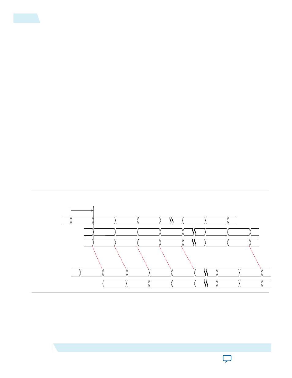
Figure 3-11: AUX Interface Transmit Write Latency
Illustrates the transmit write latency on the AUX interface when Auxiliary latency cycle(s) has the value
of 0. If you specify a non-zero value for this parameter, the latency increases from the default latency of
one
cpri_clkout
cycle to 1 plus the number of cycles you specify.
In this example, the CPRI line bit rate is 6.144 Gbps, so that the control word is 10 bytes. User logic masks
the control word, so that the IP core does not receive the control words from the AUX interface.
aux_tx_seq[5:0]
internal tx_seq value[5:0]
CPRI Frame
2
1
0
3
39
39
38
38
Ct rl
Ct rl
{Ctrl,feed}
0
1
2
3
39
38
39
aux_tx_mask[31:0]
aux_tx_data[31:0]
0000ffff
ffffffff
00000000
00000000
ffffffff
ffffffff
0000feed
abcdabcd
abcdabcd
00000000
00000000
1 cpri_clkout cycle
default write latency
Direct Interface CPRI Frame Data Format
The information on the AUX interface and all of the other direct interfaces except the L1 CSR interface,
appears in the relevant data bus in 32-bit words. The CPRI v6.0 IP core converts the contents of the
incoming CPRI frame to a 32-bit format internally. Similarly, the IP core expects to receive data on the
3-18
Direct Interface CPRI Frame Data Format
UG-01156
2014.08.18
Altera Corporation
Functional Description