Setup elements, Setup elements –19 – Altera Stratix V Advanced Systems Development Board User Manual
Page 29
Chapter 2: Board Components
2–19
Configuration, Status, and Setup Elements
January 2014
Altera Corporation
Stratix V Advanced Systems Development Board
Reference Manual
Setup Elements
The development board includes several different kinds of setup elements. This
section describes the following setup elements:
■
Board settings DIP switch
■
JTAG control DIP switch
■
PCI Express control DIP switch
■
MAX V reset push button
■
Program load push button
■
Program select push button
■
CPU reset push buttons
f
For more information about the DIP switch settings, refer to the
.
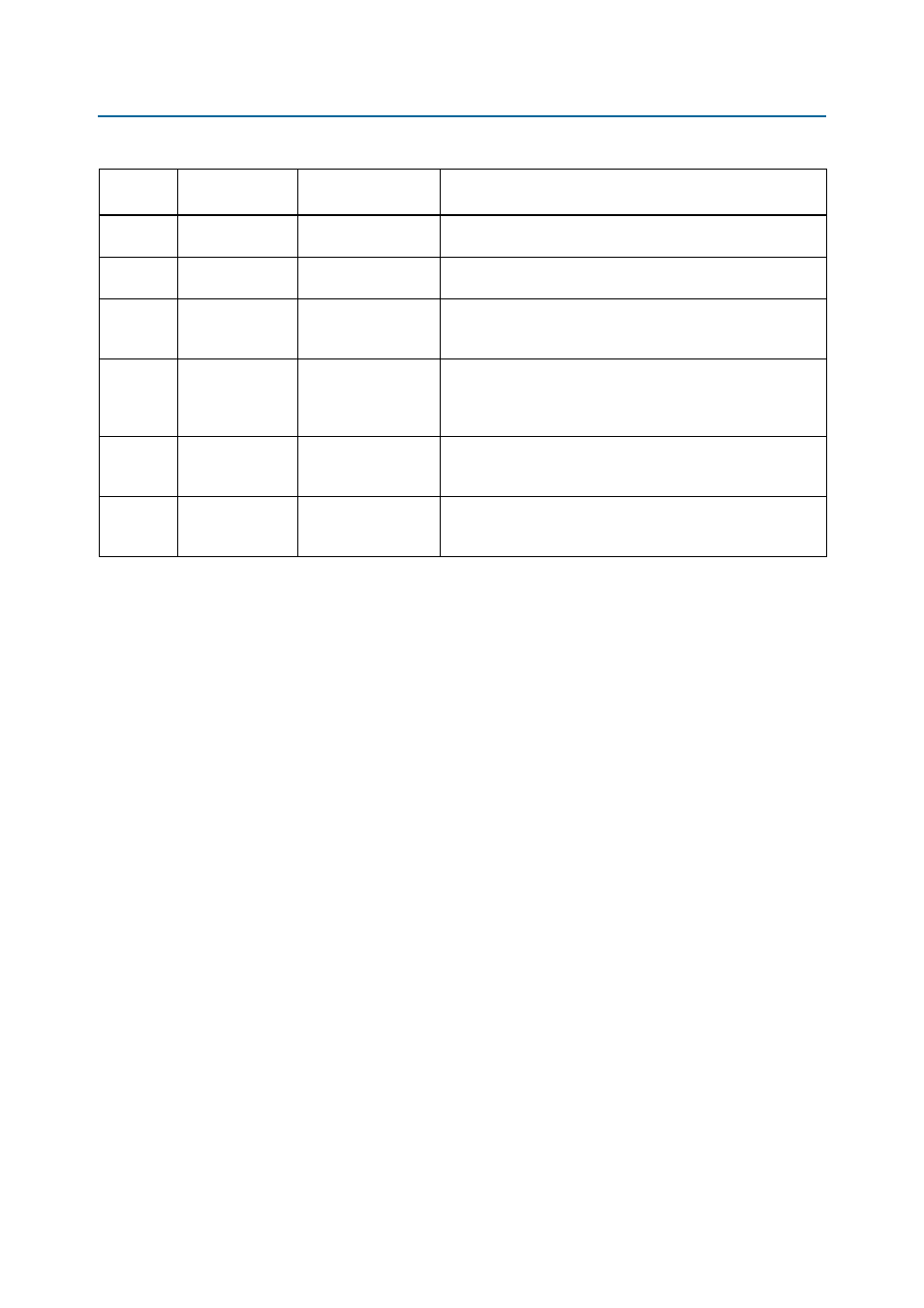
D10
RX
HSMC_RX_LED
Green LED. Blinks to indicate HSMC receive activity. Driven by
FPGA2.
D11
TX
HSMC_TX_LED
Green LED. Blinks to indicate HSMC transmit activity. Driven by
FPGA2.
D21
PRSNTn
HSMC_PRSNTn
Green LED. Illuminates when the HSMC port has a board or
cable plugged-in such that pin 160 becomes grounded. Driven
by the add-in card.
D1, D2, D3 PGM_LED[2:0]
PGM_LED0
PGM_LED1
PGM_LED2
The sequence displayed determines which design is used to
configure the FPGAs from flash when you press the PGM_LOAD
push button. Refer to
for the push button
configuration settings.
D26
OVERTEMP
FPGA1
FPGA1_OVERTEMPn
Red LED. Illuminates when a heat sink or fan should be installed.
Driven by the MAX1619 thermal sensor FPGA1_OVERTEMPn
signal.
D37
OVERTEMP
FPGA2
FPGA2_OVERTEMPn
Red LED. Illuminates when a heat sink or fan should be installed.
Driven by the MAX1619 thermal sensor FPGA2_OVERTEMPn
signal.
Table 2–8. Board-Specific LEDs (Part 2 of 2)
Board
Reference
LED Name
Schematic Signal
Name
Description