3 vdl control panel – BINDER VD 23 User Manual
Page 26
Advertising
VDL (E2.1) 04/2014
page 26/107
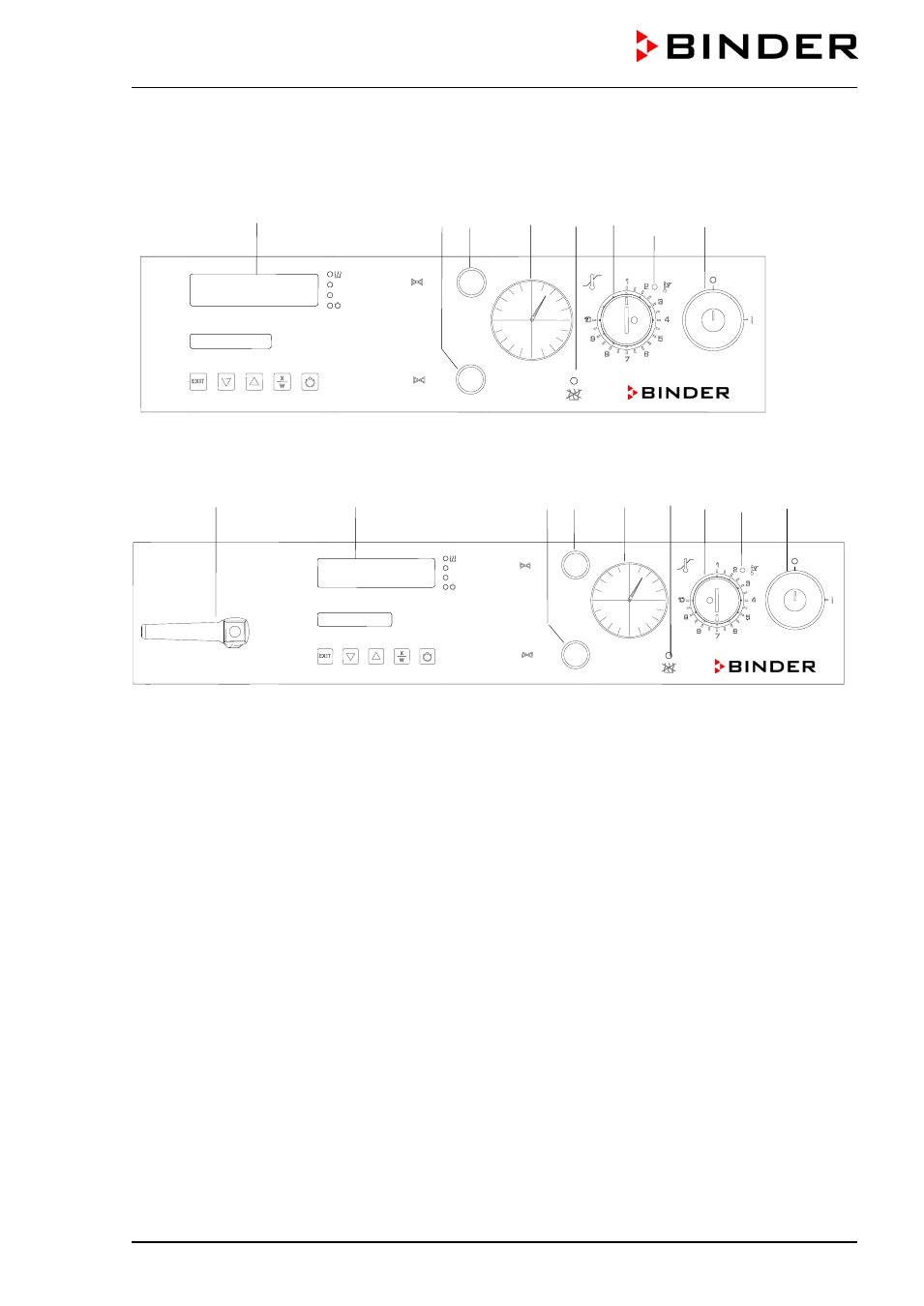
2.3 VDL control panel
(7) (6) (5) (3) (4) (2) (2a) (1)
Figure 5: VDL 23 control panel
(8) (7) (6) (5) (3) (4) (2) (2a) (1)
Figure 6: VDL 53/115 control panel
(1)
Key switch (main power switch)
(2)
Temperature safety device class 2
(2a) Red alarm lamp of the safety device class 2
(3)
Manometer (pressure reading)
(4)
Yellow pilot light: No heating release
(5)
Aeration valve (ambient air)
(6)
Fine dosing valve (inert gas)
(7)
Program controller RD3
(8)
Vacuum shut-off valve
AIR
GAS
VAC.OFF
VAC.ON
AIR
GAS
Advertising