9 navigation keys, 10 buttons for drop-down menus, 11 icons – CIRCUTOR AR6 Series User Manual
Page 11: 12 screen, 3 connectors, 1 voltage inputs, 2 current inputs, 3 usb port, Navigation keys, Buttons for drop-down menus
AR6 portable network analyzer
User Manual
Page 11 of 69
2.2.9 Navigation keys
The unit has 4 navigation keys. These buttons have arrows drawn on them to indicate the
direction of cursor movement. In this manual these buttons are referred to with the
▲/▼, ◄/►
icons.
2.2.10 Buttons for drop-down menus
The analyzer function buttons are variable or "dynamic". The options displayed on dropping
down the menus for each of the function buttons are, different depending on the current screen.
2.2.11 Icons
The main menu icons help the user quickly and easily access the configuration, system
information and display screens. For more information on each of the shortcut icons see chapter
18 entitled SCREEN INFORMATION
2.2.12 Screen
5.7” VGA LCD screen that can simultaneously display data from 9 channels: Voltages U1, U2,
U3 , phase to neutral (terminal UN) , UN, Neutral voltage referred to earth (terminal U
EARTH
) and
currents I1, I2, I3, IN, I
LEAK
.
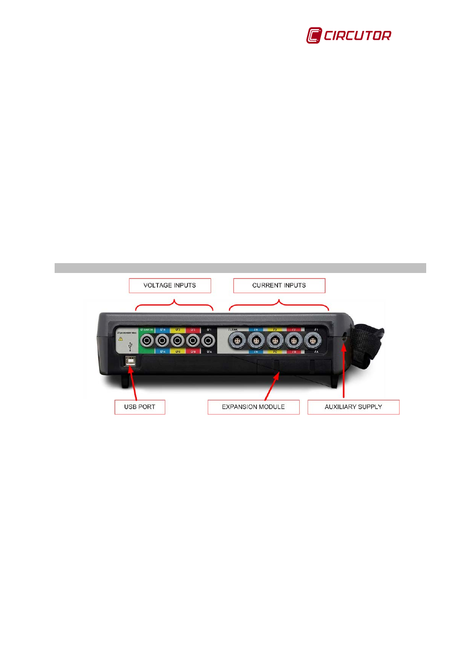
2.3
CONNECTORS
Fig.2-3.- Connections on the top of the AR6
2.3.1 Voltage inputs
The voltage inputs of the AR6 are found on the top part of the unit, as shown in Fig.2-3. They
are identified with the symbols U1 (U
A
), U2 (U
B
), U3 (U
C
), U
N
(U
N
) and Uearth and identified
with different colours (identifier adhesive label may be chosen by the user).
2.3.2 Current inputs
The analyzer's current inputs are also found on the top of the analyzer, as shown in Fig.2-3.
This current inputs are identified with the symbols I1 (I
A
), I2 (I
B
), I3 (I
C
), I
N
(I
N
) and I
LEAK
. The
identification colours depend on the identifier adhesive chosen by the user.
2.3.3 USB port
This is a type B USB communications port, used for downloading recorded data. When the
analyzer is connected to a computer, the unit is recognized as an external drive, so it is not
necessary to communicate with the unit in order to download stored files, simply drag the files to
the desired directory of the computer or download them using the PowerVisionPlus® software.