Rms values, 6 trigger interval, Trigger interval – CIRCUTOR AR6 Series User Manual
Page 33
AR6 portable network analyzer
User Manual
Page 33 of 69
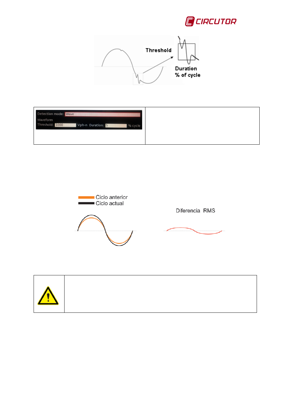
Fig.10-12.- Wave shape defect
Fig. 10-13.- Wave shape defect configuration
screen
Configurable Parameters:
•
Threshold in V , phase to neutral
•
Duration in % of the cycle
RMS Values
The detection of transients based on RMS values is achieved by comparing the value of each
cycle of each channel with the RMS value of the previous cycle of the same channel. If the
difference between RMS values exceeds that configured by the user, the current cycle is logged
as a defect. The user can program a difference of between 30 and 800 V
RMS
.
Fig.10-14.- Difference in RMS value defect
Disabled: This option lets the user disable the detection of transients
The transients log is automatically disabled for 10 minutes when it detects more
than 1 transient/second in 15 seconds. This deactivation process is repeated 5
times, after which the log is permanently disabled to prevent a bad transient
detection configuration from filling up the analyzer's internal memory.
10.2.6 Trigger interval
The trigger interval menu lets the user configure the start and end dates and times to activate
the data logging.