2 measurement configuration, Measurement configuration – CIRCUTOR AR6 Series User Manual
Page 29
AR6 portable network analyzer
User Manual
Page 29 of 69
connected current sensors and shows their scale. If multi-scale sensors are connected, the user
must select manually the desired one. The analyzer shows one by default. The current ratios
can also be modified if the user is measuring at the secondary of a 5A transformer with 5
Ampere clamps, but wishes to view the values measured with respect to the primary of the
installation. Similarly, the ratio by default of the voltage transformer is 1/1. If this is not the case,
the primary and secondary voltages must be programmed for the voltage transformers.
The device recognises single-scale current clamps and configures them
automatically. The AR6 only allows configuration of the current transformer’s ratio if
it detects multi-scale clamps or 5 A primary clamps. For all other cases, it
automatically recognises the clamps and configures the current scale
10.2.2 Measurement configuration
Configuring a measurement involves the creation of a folder where all the configuration files and
data records will be saved.
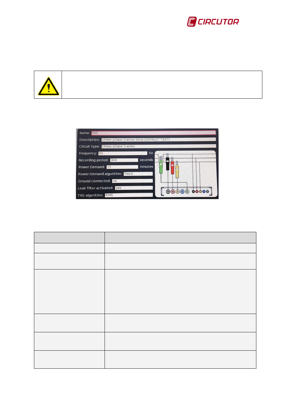
Fig.10-5.- Measurement configuration screen (Example)
The configurable fields on the Measurement screen are:
Table 10-1.- Configurable fields on the measurement screen
Option
Description
Name
Name of the measurement.
Description
Description of the measurement. Lets the user indicate specific
data to facilitate locating or referencing the measurement.
Circuit type
Indicates the configuration of the measurement. The user can
select between:
• Single-phase
• Two-phases
• Three-phases, 3-wire
• ARON three-phase, 3-wire
• Three-phase, 4-wire
Nominal frequency
[50…60 Hz]
Nominal frequency of the network where the measurement is
being taken. The user can select 50 or 60 Hz
Log period
[1…7,200 seconds
The log period for the electrical parameters (in seconds). This
period is commonly used as averaging period for the variables.
Maximum demand
[minutes]
In this field the user should program the energy integration
time to perform the Maximum Demand calculation.