Marantz AV8003 User Manual
Page 16
SETUP
BASIC
OPERA
TION
ADV
ANCED
OPERA
TION
REMOTE
CONTROLLER
TROUBLESHOOTING
OTHERS
NAMES AND
FUNCTION
CONNECTIONS
ENGLISH
13
L
L
SR
SR
R
R
R
R
SR
SR
SL
SL
SW
SW
C
C
SBR
SBR
SBL
SBL
L
L
SBL
SBL
SW
SW
SBR
SBR
FM
FM (
(75
75
Ω
Ω))
GND
GND
AM
AM
ANTENNA
ANTENNA
OUT
OUT
PUT
PUT
1
1
OUT
OUT
PUT
PUT
2
2
INPUT 3
INPUT 3((VCR1
VCR1))
OUTPUT 1
OUTPUT 1
OUTPUT 2
OUTPUT 2
INPUT 1
INPUT 1(
(TV
TV)
)
INPUT 4
INPUT 4((DSS/VCR2
DSS/VCR2))
INPUT 2
INPUT 2(
(DVD
DVD)
)
COMPONENT
COMPONENT
VIDEO
VIDEO
C
CB
B
//
P
PB
B
C
CR
R
//
P
PR
R
C
CR
R
//
P
PR
R
C
CR
R
//
P
PR
R
C
CB
B
//
P
PB
B
C
CB
B
//
P
PB
B
Y
Y
Y
Y
Y
Y
INPUT 1
INPUT 1(
(TV
TV)
)
INPUT 4
INPUT 4(
(DSS
DSS // VCR2
VCR2)
)
INPUT 3
INPUT 3(
(VCR1
VCR1)
)
INPUT 2
INPUT 2((DVD
DVD))
RS-232C
RS-232C
SPEAKER C
SPEAKER C
SIRIUS
SIRIUS
ON
ON OFF
OFF
AC IN
AC IN
OUT
OUT
IN
IN
IN
IN
OUT
OUT
VIDEO
VIDEO
MONITOR
MONITOR
OUT
OUT
DVD
DVD(
(2
2)
)
DSS/VCR2
DSS/VCR2(
(4
4)
)
TV
TV(
(1
1)
)
ZONE
ZONE
OUT
OUT
VCR1
VCR1(
(3
3)
)
DVD
DVD((2
2))
TV
TV(
(1
1)
)
2
2
1
1
FLASHER
FLASHER
IN
IN
IR
IR
RECEIVER
RECEIVER
IN
IN
6
6
COAX.
COAX.
5
5
4
4
OUT
OUT
IN
IN
1
1
2
2
EMITTER
EMITTER
OUT
OUT
SELECTOR
SELECTOR
DC OUT
DC OUT
R
R
L
L
OUT
OUT
R
R
OUT
OUT
L
L
TAPE
TAPE
OUT
OUT
IN
IN
R
R
OUT
OUT
L
L
DSS/VCR2
DSS/VCR2
AUDIO
AUDIO
BALANCED
BALANCED
PRE OUT
PRE OUT
UNBALANCED
UNBALANCED
TV
TV
IN
IN
SR
SR
VCR1
VCR1
IN
IN
DVD
DVD
SL
SL
SBR
SBR
SBL
SBL
SW
SW
C
C
A
A
B
B
7.1CH
7.1CH
IN
IN
(
(AUX
AUX)
)
3
3
2
2
1
1
OPT.
OPT.
MOD
MODEL NO. AV8003
DIGITAL IN
DIGITAL IN
DIGITAL OUT
DIGITAL OUT
MAIN
MAIN
ZONE
ZONE
CD/CDR
CD/CDR
IN
IN
REMOTE
REMOTE
1
2
3
BALANCED
BALANCED
UNBALANCED
UNBALANCED
IN
IN
OUT
OUT
S-VIDEO
S-VIDEO
IN
IN
OUT
OUT
DSS/VCR2
DSS/VCR2(
(4
4)
)
VCR1
VCR1(
(3
3)
)
MONI. OUT
MONI. OUT
CD/CDR BALANCED IN
CD/CDR BALANCED IN
ZONE OUT
ZONE OUT
CONNECTION
GND
HOT(+)
COLD(-)
3
2
1
PUSH
PUSH
OUT
OUT
R
R
L
L
AUDIO
AUDIO
TV
TV
IN
IN
VCR1
VCR1
DVD
DVD
2
2
DVD
DVD(
(2
2)
)
IN
IN
OUT
OUT
VCR1
VCR1(
(3
3)
)
DVD
DVD((2
2))
INPUT 2
INPUT 2((DVD
DVD))
OUT
OUT
PUT
PUT
1
1
C
CR
R
//
P
PR
R
C
CB
B
//
P
PB
B
Y
Y
COMPONENT
COMPONENT
VIDEO
VIDEO
INPUT 4
INPUT 4(
(DSS
DSS // VCR2
VCR2)
)
C
CR
R
//
P
PR
R
C
CB
B
//
P
PB
B
Y
Y
IN
IN
OUT
OUT
DSS/VCR2
DSS/VCR2(
(4
4)
)
VCR1
VCR1(
(3
3)
)
MONI. OUT
MONI. OUT
S-VIDEO
S-VIDEO
DIGITAL IN
DIGITAL IN
VIDEO
VIDEO
L R
AUDIO
OUT
DIGITAL
OUT
VIDEO
OUT
S-VIDEO
OUT
S-VIDEO
IN
L R
AUDIO
OUT
AUDIO
IN
L R
VIDEO
OUT IN
S-VIDEO
OUT IN
Y C
B
/
P
B
C
R
/
P
R
COMPONENT
VIDEO OUT
Y C
B
/
P
B
C
R
/
P
R
COMPONENT
VIDEO IN
L
R
L R L R
L
R
L
L
R
R
R
R
SR
SR
SW
SW
SBR
SBR
FM
FM (
(75
75
Ω
Ω))
GND
GND
AM
AM
ANTENNA
ANTENNA
OUT
OUT
PUT
PUT
1
1
OUT
OUT
PUT
PUT
2
2
INPUT 3
INPUT 3((VCR1
VCR1))
OUTPUT 1
OUTPUT 1
OUTPUT 2
OUTPUT 2
INPUT 1
INPUT 1(
(TV
TV)
)
INPUT 4
INPUT 4((DSS/VCR2
DSS/VCR2))
INPUT 2
INPUT 2(
(DVD
DVD)
)
COMPONENT
COMPONENT
VIDEO
VIDEO
C
CB
B
//
P
PB
B
C
CR
R
//
P
PR
R
C
CR
R
//
P
PR
R
C
CR
R
//
P
PR
R
C
CB
B
//
P
PB
B
C
CB
B
//
P
PB
B
Y
Y
Y
Y
Y
Y
INPUT 1
INPUT 1(
(TV
TV)
)
INPUT 4
INPUT 4(
(DSS
DSS // VCR2
VCR2)
)
INPUT 3
INPUT 3(
(VCR1
VCR1)
)
INPUT 2
INPUT 2((DVD
DVD))
OUT
OUT
IN
IN
IN
IN
OUT
OUT
VIDEO
VIDEO
MONITOR
MONITOR
OUT
OUT
DVD
DVD(
(2
2)
)
DSS/VCR2
DSS/VCR2(
(4
4)
)
TV
TV(
(1
1)
)
ZONE
ZONE
OUT
OUT
VCR1
VCR1(
(3
3)
)
DVD
DVD((2
2))
TV
TV(
(1
1)
)
2
2
1
1
FLASHER
FLASHER
IN
IN
IR
IR
RECEIVER
RECEIVER
IN
IN
6
6
COAX.
COAX.
5
5
4
4
OUT
OUT
IN
IN
1
1
2
2
EMITTER
EMITTER
OUT
OUT
SELECTOR
SELECTOR
DC OUT
DC OUT
R
R
L
L
OUT
OUT
R
R
OUT
OUT
L
L
TAPE
TAPE
OUT
OUT
IN
IN
R
R
OUT
OUT
L
L
DSS/VCR2
DSS/VCR2
AUDIO
AUDIO
UNBA
UNBALANCED
TV
TV
IN
IN
SR
SR
VCR1
VCR1
IN
IN
DVD
DVD
SL
SL
SBR
SBR
SBL
SBL
SW
SW
C
C
A
A
B
B
7.1CH
7.1CH
IN
IN
(
(AUX
AUX)
)
3
3
2
2
1
1
OPT.
OPT.
DIGITAL IN
DIGITAL IN
DIGITAL OUT
DIGITAL OUT
MAIN
MAIN
ZONE
ZONE
CD/CDR
CD/CDR
IN
IN
REMOTE
REMOTE
1
2
3
BALANCED
BALANCED
UNBALANCED
UNBALANCED
IN
IN
OUT
OUT
S-VIDEO
S-VIDEO
IN
IN
OUT
OUT
DSS/VCR2
DSS/VCR2(
(4
4)
)
VCR1
VCR1(
(3
3)
)
MONI. OUT
MONI. OUT
CD/CDR BALANCED IN
CD/CDR BALANCED IN
ZONE OUT
ZONE OUT
CONNECTION
GND
HOT(+)
COLD(-)
3
2
1
PUSH
PUSH
TV
TV(
(1
1)
)
4
4
R
R
L
L
TV
TV
AUDIO
AUDIO
DSS/VCR2
DSS/VCR2
IN
IN
IN
IN
MONITOR
MONITOR
OUT
OUT
DSS/VCR2
DSS/VCR2(
(4
4)
)
VIDEO
VIDEO
DIGITAL IN
DIGITAL IN
IN
IN
DSS/VCR2
DSS/VCR2(
(4
4)
)
MONI. OUT
MONI. OUT
S-VIDEO
S-VIDEO
L R
AUDIO
OUT
DIGITAL
OUT
VIDEO
OUT
S-VIDEO
OUT
AUDIO
OUT
L R
VIDEO
OUT
S-VIDEO
IN
VIDEO
IN
L
R
L
R
L R
L
R
L
R
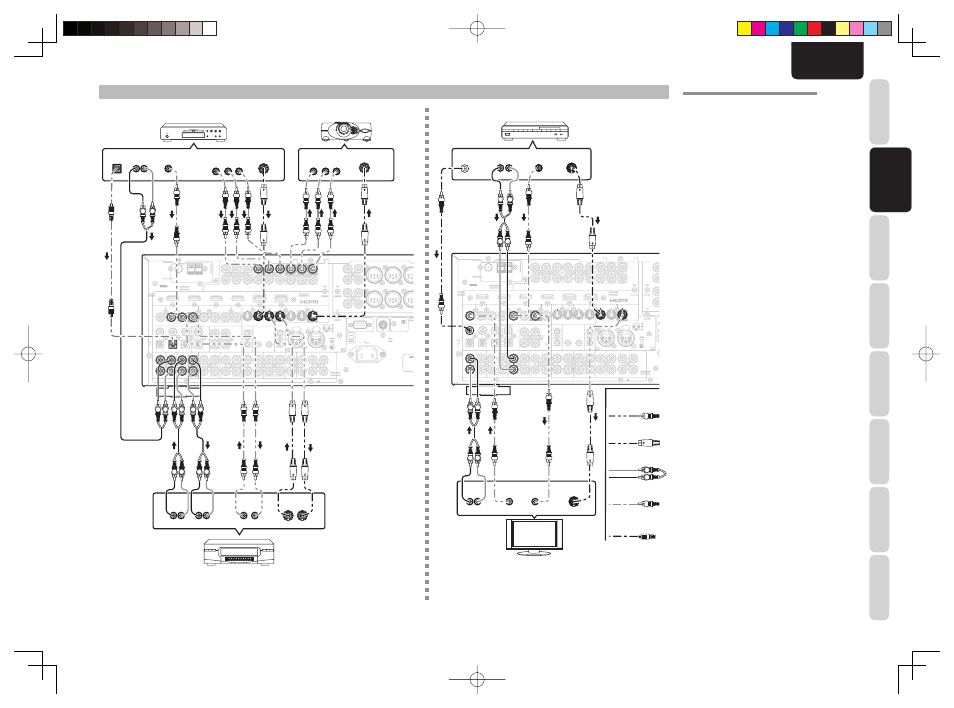
CONNECTING VIDEO COMPONENTS
Analog Audio
Video
S-Video
DVD player
VIDEO
PROJECTOR
Satellite Tuner
Digital Audio
(coaxial)
VCR
TV
VIDEO, S-VIDEO, COMPONENT JACKS
There are 3 types of video jacks on the rear panel.
VIDEO jack
The video signal for the VIDEO jacks is the
conventional composite video signal.
S-VIDEO jack
The video signal is separated into luminance (Y) and
color (C) signals for the S-VIDEO jack. The S-VIDEO
signals enables high-quality color reproduction.
Connect the S-VIDEO output jack on your video
component to the S-VIDEO input jack on this unit.
Component jack
Make component video connections to a TV or
monitor with component inputs to produce higher
quality video images. Use a component video cable
or 3 video cords to connect the component video out
jacks on the unit to the monitor.
Notes:
• Be sure to connect the left and right audio channels
properly.
Red connectors are for the R (right) channel, and
white connectors are the for L (left) channel.
• Be sure to connect the inputs and outputs of the
video signals properly.
• If you connect the S-VIDEO or component signal to
the S-VIDEO or component jack on this unit, it is not
necessary to connect the conventional video signal to
the VIDEO (composite) jack. If you use both video
inputs, this unit gives priority to the S-VIDEO signal.
• Each type of video jack works independently.
Signals input to the VIDEO (composite) and S-
VIDEO jacks or component are output to the
corresponding VIDEO (composite) and S-VIDEO
or component jacks, respectively.
• This unit has the “TV-AUTO ON/OFF” function to
turn the TV ON or OFF automatically, by sensing the
incoming video signal from the VIDEO jacks.
• You may need to setup the digital audio output
format of your DVD player, or other digital source
components. Refer to the instructions of the each
component connected to the digital input jacks.
• There is no Dolby Digital RF input jack. Use an
external RF demodulator with a Dolby Digital
decoder to connect the Dolby Digital RF output jack
of the DVD player to the digital input jack on this
unit.
• The COMPONENT OUTPUT 1 and 2 terminals of
this unit can output the same video signal. Moreover,
the OUTPUT 2 terminal of the unit can output video
signals for zone playback. (See page 34)
Digital Audio
(optical)
AV8003_U_Eng.indb 13
AV8003_U_Eng.indb 13
08.4.28 10:40:07 AM
08.4.28 10:40:07 AM