Marantz AV8003 User Manual
Page 19
SETUP
BASIC
OPERA
TION
ADV
ANCED
OPERA
TION
REMOTE
CONTROLLER
TROUBLESHOOTING
OTHERS
NAMES AND
FUNCTION
CONNECTIONS
ENGLISH
16
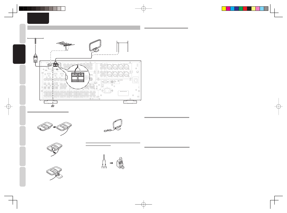
CONNECTING THE ANTENNA TERMINALS
L
L
SR
SR
SL
SL
R
R
R
R
SR
SR
SL
SL
SW
SW
C
C
SBR
SBR
SBL
SBL
L
L
SBL
SBL
SW
SW
C
C
SBR
SBR
FM
FM (
(75
75
Ω
Ω))
GND
GND
AM
AM
ANTENNA
ANTENNA
OUT
OUT
PUT
PUT
1
1
OUT
OUT
PUT
PUT
2
2
INPUT 3
INPUT 3((VCR1
VCR1))
OUTPUT 1
OUTPUT 1
OUTPUT 2
OUTPUT 2
INPUT 1
INPUT 1(
(TV
TV)
)
INPUT 4
INPUT 4((DSS/VCR2
DSS/VCR2))
INPUT 2
INPUT 2(
(DVD
DVD)
)
COMPONENT
COMPONENT
VIDEO
VIDEO
C
CB
B
//
P
PB
B
C
CR
R
//
P
PR
R
C
CR
R
//
P
PR
R
C
CR
R
//
P
PR
R
C
CB
B
//
P
PB
B
C
CB
B
//
P
PB
B
Y
Y
Y
Y
Y
Y
INPUT 1
INPUT 1(
(TV
TV)
)
INPUT 4
INPUT 4(
(DSS
DSS // VCR2
VCR2)
)
INPUT 3
INPUT 3(
(VCR1
VCR1)
)
INPUT 2
INPUT 2((DVD
DVD))
RS-232C
RS-232C
SPEAKER C
SPEAKER C
SIRIUS
SIRIUS
NETWORK
NETWORK
ON
ON OFF
OFF
1
3
CONNECTION
GND
HOT(+)
COLD(-)
3
2
1
2
AC IN
AC IN
OUT
OUT
IN
IN
IN
IN
OUT
OUT
VIDEO
VIDEO
MONITOR
MONITOR
OUT
OUT
DVD
DVD(
(2
2)
)
DSS/VCR2
DSS/VCR2(
(4
4)
)
TV
TV(
(1
1)
)
ZONE
ZONE
OUT
OUT
VCR1
VCR1(
(3
3)
)
DVD
DVD((2
2))
TV
TV(
(1
1)
)
2
2
1
1
FLASHER
FLASHER
IN
IN
IR
IR
RECEIVER
RECEIVER
IN
IN
6
6
COAX.
COAX.
5
5
4
4
OUT
OUT
IN
IN
1
1
2
2
EMITTER
EMITTER
OUT
OUT
SELECTOR
SELECTOR
DC OUT
DC OUT
R
R
L
L
OUT
OUT
R
R
OUT
OUT
L
L
TAPE
TAPE
OUT
OUT
IN
IN
R
R
OUT
OUT
L
L
DSS/VCR2
DSS/VCR2
AUDIO
AUDIO
BALANCED
BALANCED
PRE OUT
PRE OUT
UNBALANCED
UNBALANCED
TV
TV
IN
IN
SR
SR
VCR1
VCR1
IN
IN
DVD
DVD
SL
SL
SBR
SBR
SBL
SBL
SW
SW
C
C
A
A
B
B
7.1CH
7.1CH
IN
IN
(
(AUX
AUX)
)
3
3
2
2
1
1
OPT.
OPT.
MODEL NO. AV8003
MODEL NO. AV8003
DIGITAL IN
DIGITAL IN
DIGITAL OUT
DIGITAL OUT
MAIN
MAIN
ZONE
ZONE
CD/CDR
CD/CDR
IN
IN
REMOTE
REMOTE
1
2
3
BALANCED
BALANCED
UNBALANCED
UNBALANCED
IN
IN
OUT
OUT
S-VIDEO
S-VIDEO
IN
IN
OUT
OUT
DSS/VCR2
DSS/VCR2(
(4
4)
)
VCR1
VCR1(
(3
3)
)
MONI. OUT
MONI. OUT
CD/CDR BALANCED IN
CD/CDR BALANCED IN
ZONE OUT
ZONE OUT
CONNECTION
GND
HOT(+)
COLD(-)
3
2
1
PUSH
PUSH
FM
FM (
(75
75
Ω
Ω))
GND
GND
AM
AM
ANTENNA
ANTENNA
FM ( 5
75
Ω
Ω))
GND
GND
AM
AM
ANTENNA
ANTENNA
FM Feeder Antenna
FM External
Antenna
AM Loop
Antenna
AM External
Antenna
ASSEMBLING THE AM LOOP ANTENNA
1.
Release the vinyl tie and take out the connection
line.
2.
Bend the base part in the reverse direction.
3.
Insert the hook at the bottom of the loop part
into the slot at the base part.
CONNECTING THE SUPPLIED ANTENNAS
Connecting the supplied FM antenna
The supplied FM antenna is for indoor use only.
During use, extend the antenna and move it in various
directions until the clearest signal is received.
Fix it with push pins or similar implements in
the position that will cause the least amount of
distortion.
If you experience poor reception quality, an outdoor
antenna may improve the quality.
Connecting the supplied AM loop antenna
The supplied AM loop antenna is for indoor use
only.
Set it in the direction and position it to where you
receive the clearest sound. Put it as far away as
possible from the unit, televisions, speaker cables,
and power cords.
If you experience poor reception quality, an outdoor
antenna may improve the quality.
1.
Press and hold down the lever of the AM antenna
terminal.
2.
Insert the bare wire into the antenna terminal.
3.
Release the lever.
Note:
• Connect the shielded grounding wire (black) to the
AM antenna GND terminal.
CONNECTING AN FM OUTDOOR ANTENNA
Notes:
• Keep the antenna away from noise sources (neon
signs, busy roads, etc.).
• Do not put the antenna close to power lines. Keep it
well away from power lines, transformers, etc.
• To avoid the risk of lightning and electrical shock,
grounding is necessary.
CONNECTING AN AM OUTDOOR ANTENNA
An outdoor antenna will be more effective if it is
stretched horizontally above a window or outside.
Notes:
• Do not remove the AM loop antenna.
• To avoid the risk of lightning and electrical shock,
grounding is necessary.
4.
Place the antenna on stable surface.
CONNECTING THE ANTENNA WIRE TO THE
ANTENNA CONVERTER
Loosen the screws and attach the wire terminals,
then tighten the screws with a screwdriver.
Antenna
Converter
AV8003_U_Eng.indb 16
AV8003_U_Eng.indb 16
08.4.28 10:40:08 AM
08.4.28 10:40:08 AM