TE Technology TC-720 User Manual
Page 22
1.4
Connect the controller to the TE device as follows (see connection diagrams above for reference):
a) Connect wire between Positive (+) terminal of the TE device and JP7-1. Connect wire between Negative (-)
terminal of the TE device and JP7-2.
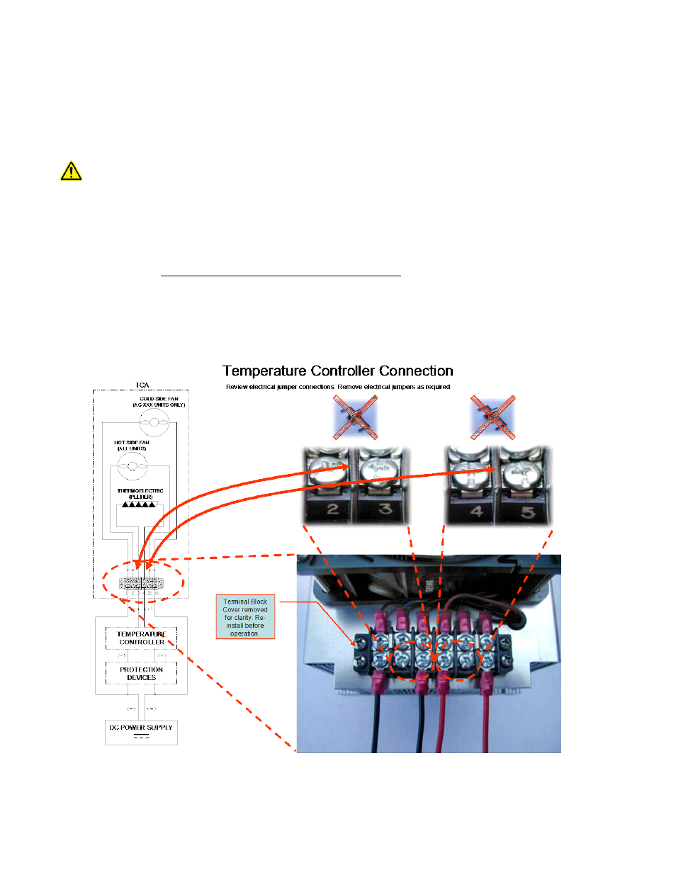
b) If a TE Technology cooler is being used, remove jumpers from the terminal block as described below.
TE Technology’s standard thermoelectric cooling assemblies (TCA) usually have at least one fan on the heat sink. The
standard configuration has the thermoelectric modules and fan(s) wired to a terminal block with jumpers across the
terminals so that the fans and TE modules are connected electrically in parallel. However, this configuration is
applicable only when applying power directly from the power supply. When using the TCA with the temperature
controller, two jumpers MUST be removed so that the controller is controlling power only to the thermoelectric
modules. There must be no electrical connection between the fans and the TE modules; fans must be connected
directly to the power supply, not to the controller (except for the fan-speed control wire in the case of using a PWM-
controlled fan). The controller will be damaged if this is not followed. See the TCA manual for further details, but
the picture below shows the basic setup.
22