TE Technology TC-720 User Manual
Page 26
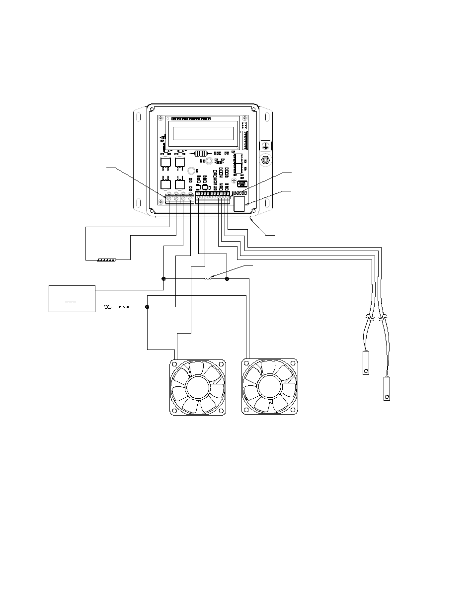
d) ALARM1 or ALARM2 outputs could also be configured to power on or off devices such pumps or fans. Each
alarm can manage up to 2 A of current. However, the total current comprised of the current passing through the
alarm outputs plus the current passing through the TE device should not be allowed to exceed 20 A.
JP7
JP2
1
2
3
4
10
9
8
7
6
5
4
3
2
1
(+)
(-)
TE DEVICE
DC
POWER SUPPLY
OPTIONAL FUSE
THERMOSTAT AND OTHER
PROTECTIVE DEVICES
(CUSTOMER SUPPLIED)
OPTIONAL
SECONDARY
SENSOR
JP2-4 (+) and
JP2-3(-)
CONTROL
SENSOR
JP2-1 (+) and
JP2-2 (-)
12 V, 36 V, 20 A maximum
JP7
PIN 1
JP2
PIN 1
WIRES MUST PASS THROUGH
GASKET HOLES
NOTE: LID IS REMOVED TO SHOW
WIRE CONNECTIONS
USB COMMUNICATION PORT
to JP7-1
to JP7-2
to JP7-3
to JP7-4
(+)
(-)
(+)
(-)
(+)
(-)
SUGGESTED
VOLTAGE DROPPING
RESISTOR FOR ALTERNATIVE
FAN SPEED CONTROL
to JP2-8
(ALARM1)
to JP2-10
(ALARM2)
≤
≥
26