TE Technology TC-720 User Manual
Page 57
The HIGH ALARM 2 SETTING, LOW ALARM 2 SETTING, and ALARM 2 DEADBAND function in the same manner as described
above for ALARM 1 settings except that they are referenced to the secondary sensor.
FAN CONTROL CONFIGURATION
PRINCIPAL OF OPERATION: Fan speed control is designed to adjust the speed of the heat sink fan only. It allows the fan to
operate at reduced speeds, and is used when the resulting loss of cooling capacity during speed regulation is an acceptable
tradeoff for achieving lower fan noise. The fan speed is modified as a function of the percentage of output power being
commanded to the TE device (main output%).
Fan speed is controlled by generating a PWM signal with the Alarm 1 output transistor. This is an open-drain field effect
transistor. The Alarm 1 terminal (JP2-8) is either electrically shorted to ground or allowed to remain open relative to
ground to achieve the desired control.
The “FAN CONTROL+” setting causes the Alarm 1 output to be electrically shorted to ground at an increasingly higher rate
when a faster fan speed is desired. The “FAN CONTROL-” setting causes the Alarm 1 output to be electrically open to
ground at an increasingly higher rate when a faster fan speed is desired. The appropriate setting is dependent on the fan.
When using a two-wire fan, the negative fan wire is typically attached to the Alarm 1 terminal (JP2-8), and increasing the
amount of time that the transistor is shorted to ground will increase the fan speed. You would use “FAN CONTROL+” for this
set up. Conversely, when the fan includes a separate terminal for speed control, a higher fan speed is typically achieved by
decreasing the amount of time the speed control terminal is shorted to ground. This is not an absolute convention among
fan manufacturers, so consult the fan manufacturer’s specification for proper operating instructions. Additionally, if the fan
does not include an internal pull-up resistor on the speed control terminal, an external pull-up resistor may be required.
As previously mentioned, two-wire fans are not ordinarily designed for fan-speed control in this fashion. Consult with the fan
manufacturer to verify whether PWM can be used with the fan before using this feature.
The “FAN CONTROL SETTINGS” below dictate how the PWM signal generated by the Alarm 1 output transistor relative to
output power being commanded to the thermoelectric device (main output%).
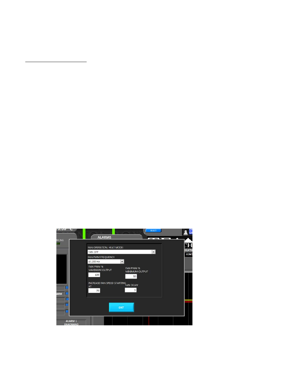
Clicking the “FAN CONTROL SETTINGS” ADJUST button brings up the following screen:
57