TE Technology TC-720 User Manual
Page 46
The USER DEFINED sensor allows the controller to use different types of sensors. A user-programmable array of 129
locations is used to map a voltage, ranging from 0 to 5 Vdc as measured at the sensor terminals, to their corresponding
temperatures. Location 0 corresponds to 0 Vdc and location 128 corresponds to 5 Vdc. The maximum temperature range
that the CUSTOM LOOKUP TABLE will accept is from +327.68 °C to -327.68 °C. The controller will interpolate the
temperature when the reading is between two values in the table.
NOTE: The controller will sense open circuit and short circuit sensor conditions, so using sensor control ranges very close to
5V and 0V should be avoided. The main output will be turned off as a safety precaution if there is an open circuit or short
circuit sensor condition detected.
Negative or positive temperature coefficient devices can be used in the USER DEFINED sensor.
When the range will not fill the 0 to 5 volt region completely, the unused locations in the array can be filled with the
previous/last valid value.
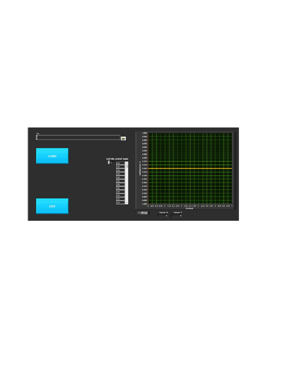
Clicking the “CONFIGURE USER DEFINED SENSOR” OK button will pop-up the screen as shown below:
The LOAD button will open the file manage where you can then select a pre-configured .csv file that contains the
temperature data. This will populate the lookup table and plot out the temperature versus sensor voltage so you can
graphically see any data entry errors.
Once the sensor has been configured, click the EXIT button. Then click the “DOWNLOAD THE USER DEFINED SENSOR TO
CONTROLLER” OK button to load the sensor profile into the controller. Clicking the “READ USER DEFINED SENSOR FROM
CONTROLLER” OK button will query the controller and report back what user defined sensor table is stored in the
controller.
Appendix C contains detailed information on creating a custom sensor curve.
46