TE Technology TC-720 User Manual
Page 48
5. Select TAB as the delimiter and click Finish
NOTE: If you want to save graphed data points to Microsoft Excel, you can use the computer mouse to right click on the
graphed data and select “Export to Microsoft Excel”.
Clicking the DOWNLOAD button next to the “DOWNLOAD FACTORY DEFAULTS” label downloads the original default
controller settings, including ramp/soak program values. You can review these settings by clicking on the INDEX scroll
arrows which will then show the DESCRIPTION of the setting and its VALUE. These default settings cannot be changed.
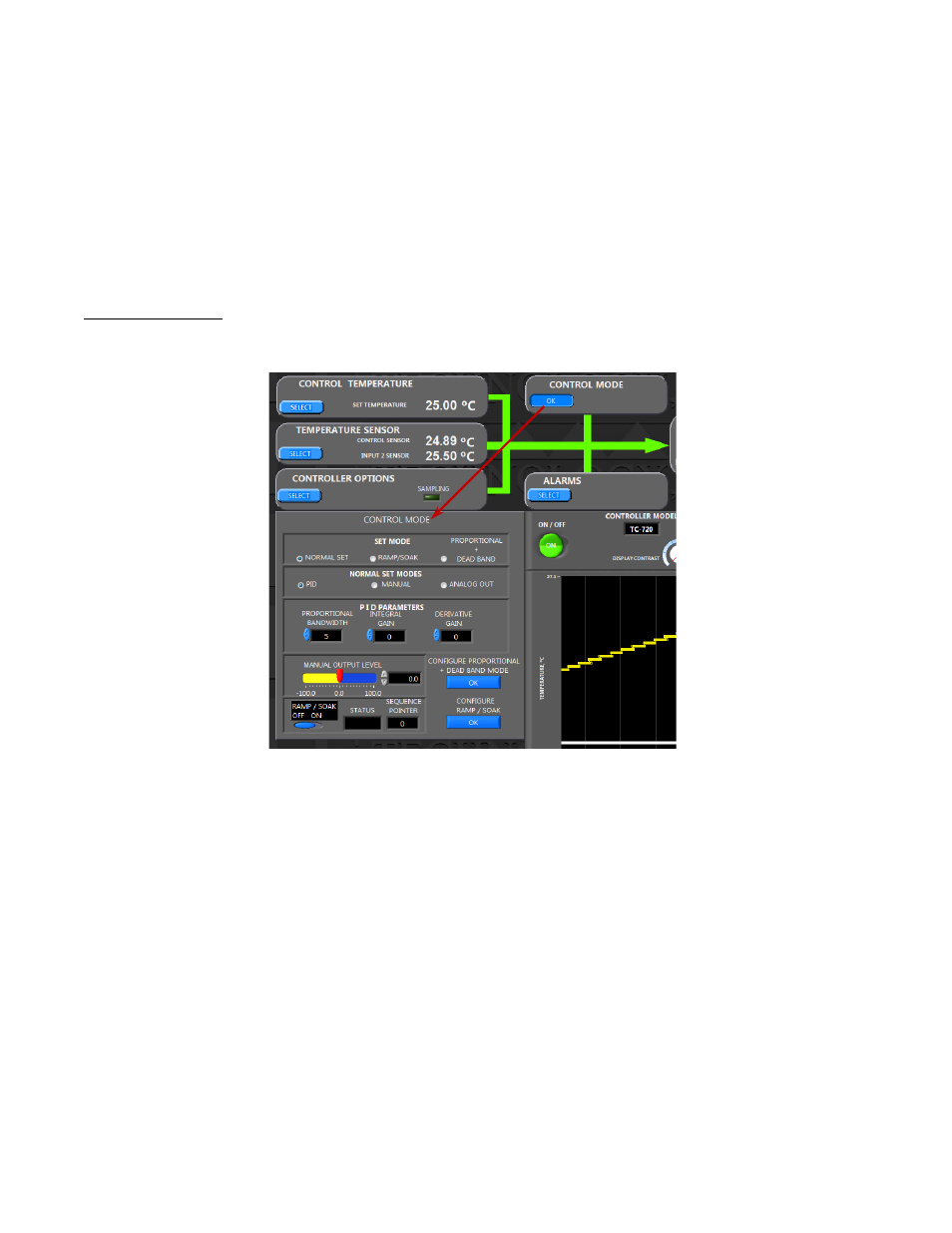
CONTROL MODE BOX
This section allows adjustment of the primary set modes, normal set modes, proportional, integral, derivative values, and
manual output level.
The controller SET MODE can be set to one of three control modes:
1. NORMAL SET—the controller will maintain either a single set point temperature or a fixed percentage output
power, or it can send an analog signal for a programmable power supply determined by the NORMAL SET MODES
selection:
i.
PID—this allows the controller to automatically control to a single set point temperature. The controller
can be tuned for control stability by adjusting the “PROPORTIONAL BANDWIDTH”, “INTEGRAL GAIN”, and
“DERIVATIVE GAIN” values in the PID PARAMETERS section. See 3.0 Controller Tuning above for
information on how to tune the controller. See also the options in the OUTPUT BOX for additional details.
ii.
MANUAL—this allows the controller to provide a fixed percentage of output power. The output power can
be set by adjusting the scale pointer in the MANUAL OUTPUT LEVEL section or by entering a percentage
output level in the box. Generally, a negative value will cause the TE device to cool, and a positive value will
cause the TE device to heat.
iii.
ANALOG OUT—this allows the controller to be used with an external, variable-voltage programmable DC
power supply to provide true analog control (not pulse width modulated control). The main difference in
ANALOG OUT mode is the output of the H-bridge is forced to always be either +100% or -100% depending
if the controller is calling for heating or cooling. There is no pulse-width modulation of the voltage that is
put into JP7-3 and JP7-4. The H-bridge circuitry within the controller is used strictly to control the polarity
of the voltage to the thermoelectric device, and is not used to vary the magnitude of that voltage. The
48