Bpdu tunneling configuration examples, Bpdu tunneling for stp configuration example, Network requirements – H3C Technologies H3C S10500 Series Switches User Manual
Page 121: Configuration procedure
110
Follow these steps to configure destination multicast MAC address for BPDUs:
To do…
Use the command…
Remarks
Enter system view
system-view
—
Configure the destination multicast
MAC address for BPDUs
bpdu-tunnel tunnel-dmac
mac-address
Optional
0x010F-E200-0003 by default
NOTE:
For BPDUs to be recognized, the destination multicast MAC addresses configured for BPDU tunneling must
be the same on the edge devices on the service provider network.
BPDU tunneling configuration examples
BPDU tunneling for STP configuration example
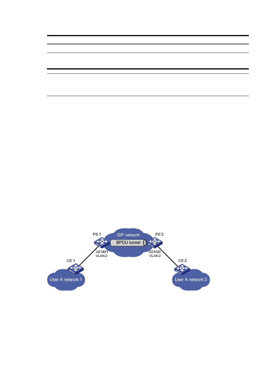
Network requirements
As shown in
:
•
CE 1 and CE 2 are edges devices on the geographically dispersed network of User A; PE 1 and PE
2 are edge devices on the service provider network.
•
All ports that connect service provider devices and customer devices are access ports and belong
to VLAN 2. All ports that interconnect service provider devices are trunk ports and allow packets of
any VLAN to pass through.
•
MSTP is enabled on User A’s network.
After the configuration, CE 1 and CE 2 must implement consistent spanning tree calculation across the
service provider network, and the destination multicast MAC address carried in BPDUs must be
0x0100-0CCD-CDD0.
Figure 33 Network diagram for configuring BPDU tunneling for STP
Configuration procedure
1.
Configure PE 1.
# Configure the destination multicast MAC address for BPDUs as 0x0100-0CCD-CDD0.
<PE1> system-view
[PE1] bpdu-tunnel tunnel-dmac 0100-0ccd-cdd0
# Create VLAN 2 and assign GigabitEthernet 1/0/1 to VLAN 2.