Ethernet link aggregation configuration examples, Layer 2 static aggregation configuration example, Network requirements – H3C Technologies H3C S10500 Series Switches User Manual
Page 61: Configuration procedure
50
To do...
Use the command...
Remarks
Clear statistics for a specific or all
aggregate interfaces
reset counters interface [ { bridge-aggregation |
route-aggregation } [ interface-number ] ]
Available in user
view
Ethernet link aggregation configuration examples
NOTE:
In an aggregation group, only ports that have the same port attributes and class-two configurations (see
“
”) as the reference port (see “
”) can operate as Selected ports. Make
sure that all member ports have the same port attributes and class-two configurations as the reference
port. The other settings only need to be configured on the aggregate interface, not on the member ports.
Layer 2 static aggregation configuration example
Network requirements
As shown in
•
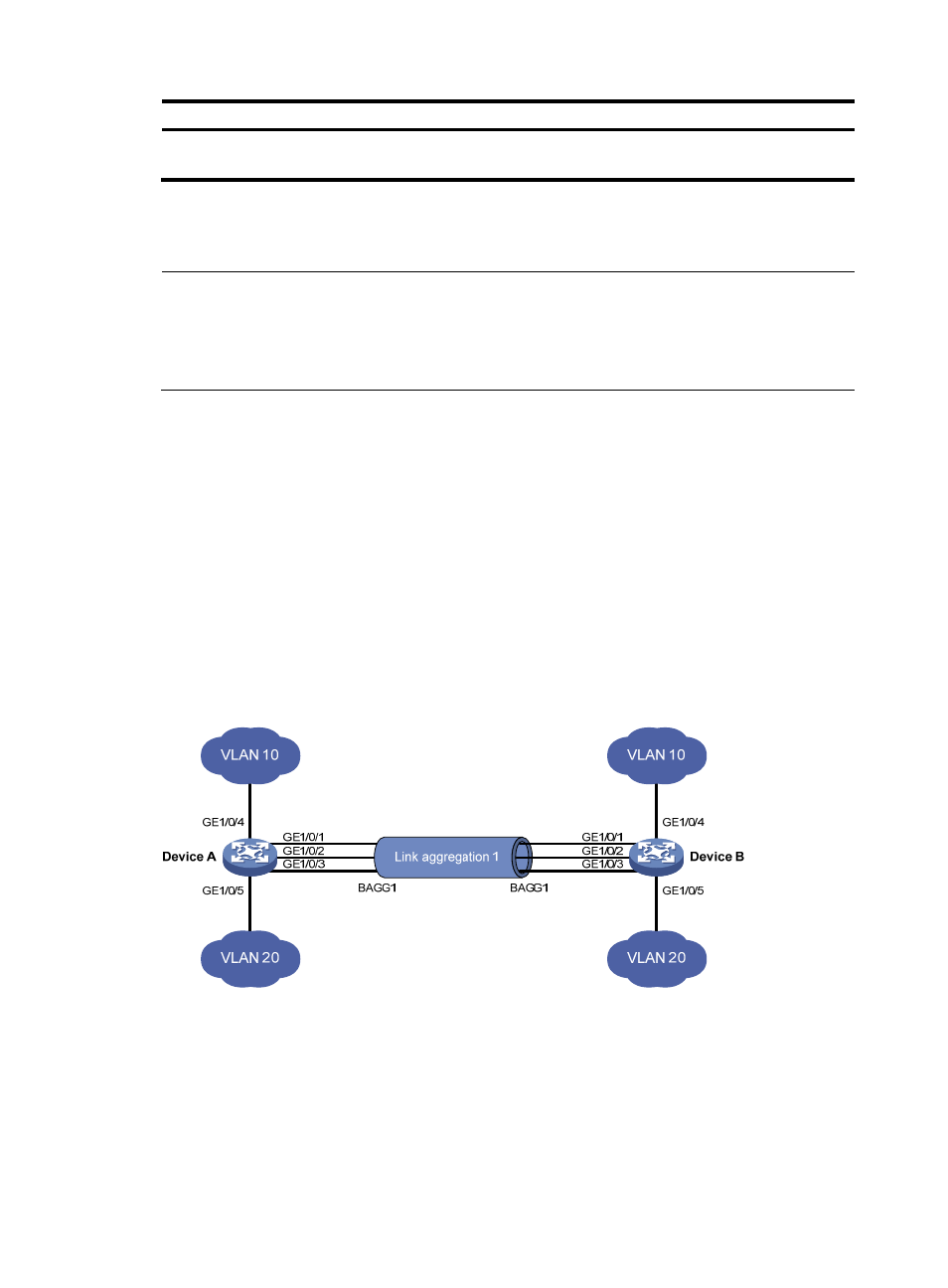
Device A and Device B are connected through their respective Layer 2 Ethernet interfaces
GigabitEthernet 1/0/1 through GigabitEthernet 1/0/3.
•
Configure a Layer 2 static aggregation group on Device A and Device B, respectively. Enable VLAN
10 at one end of the aggregate link to communicate with VLAN 10 at the other end, and VLAN 20
at one end to communicate with VLAN 20 at the other end.
•
Enable traffic to be load-shared across aggregation group member ports based on the source and
destination MAC addresses.
Figure 12 Network diagram for Layer 2 static aggregation
Configuration procedure
1.
Configure Device A
# Create VLAN 10, and assign port GigabitEthernet 1/0/4 to VLAN 10.
<DeviceA> system-view
[DeviceA] vlan 10
[DeviceA-vlan10] port gigabitethernet 1/0/4