Concepts and terms – H3C Technologies H3C S10500 Series Switches User Manual
Page 205
194
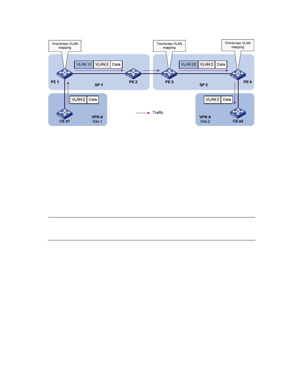
Figure 64 Application scenario of one-to-two and two-to-two VLAN mapping
Site 1 and Site 2 are in VLAN 2 and VLAN 3, respectively. The VLAN assigned for VPN A is VLAN 10
in the SP 1 network and VLAN 20 in the SP 2 network.
If Site 1 sends a packet to Site 2, the packet is processed on the way to its destination using the following
workflow:
1.
When the packet tagged with VLAN 2 arrives at the edge of network SP 1, PE 1 tags the packet
with outer VLAN 10 by using one-to-two VLAN mapping.
2.
When the double-tagged packet enters the SP 2 network, PE 3 replaces the outer VLAN tag (VLAN
10) with VLAN 20. Because the packet is destined for Site 2 in VLAN 3, PE 3 also replaces the
inner tag (VLAN 2) of the packet with VLAN 3. This process is two-to-two VLAN mapping.
3.
When PE4 receives the packet with the new VLAN tag pair, it removes the outer VLAN tag and
forwards the packet to VLAN 3.
NOTE:
You can use QinQ to implement one-to-two VLAN mapping. For more information about QinQ, see the
chapter “QinQ configuration.”
Concepts and terms
shows a simplified network to help explain the concepts and terms that you might encounter
when you work with VLAN mapping.