Configuring switch a – H3C Technologies H3C WX5500E Series Access Controllers User Manual
Page 195
185
•
Packets of VLAN 10, VLAN 20, VLAN 30, and VLAN 40 are forwarded along MSTI 1, MSTI 2,
MSTI 3, and MSTI 0, respectively.
•
Switch A and Switch B operate at the distribution layer. Switch C and Switch D operate at the access
layer. VLAN 10 and VLAN 20 are terminated on the distribution layer devices, and VLAN 30 is
terminated on the access layer devices, so the root bridges of MSTI 1 and MSTI 2 are Switch A and
Switch B, respectively, and the root bridge of MSTI 3 is Switch C.
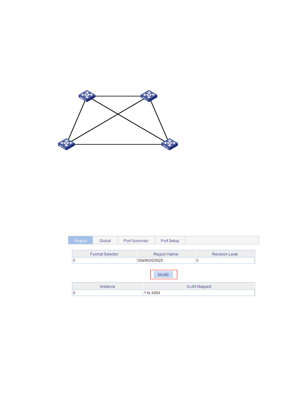
Figure 173 Network diagram
"Permit:" next to a link in the figure is followed by the VLANs the packets of which are permitted to pass
this link.
Configuring Switch A
1.
Configure an MST region:
a.
Select Network > MSTP from the navigation tree.
By default, the Region tab is displayed.
b.
Click the Modify button to enter the page for configuring MST regions.
Figure 174 The region tab
c.
Set the region name to example.
d.
Set the revision level to 0.
e.
Select the Manual option.
f.
Select 1 in the Instance ID list.
g.
Set the VLAN ID to 10.
h.
Click Apply to map VLAN 10 to MSTI 1 and add the VLAN-to-MSTI mapping entry to the
VLAN-to-MSTI mapping list.
Permit: all VLAN
Permit:
VLAN 20, 40
Permit:
VLAN 10, 40
Permit: VLAN 30, 40
Permit:
VLAN 20, 40
Permit:
VLAN 10, 40
Switch A
Switch B
Switch C
Switch D