RIGOL DG1000Z Series User Manual
Page 31
RIGOL
DG1000Z User’s Guide
1-13
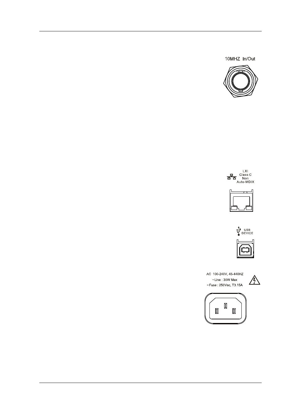
3. [10MHz In/Out]
BNC female connector with 50Ω nominal impedance.
The function of this connector is determined by the type of the
clock source.
1) When internal clock source is selected, this connector (as
10MHz Out) outputs the 10MHz clock signal generated by
the internal crystal oscillator inside the generator.
2) When external clock source is selected, this connector (as 10MHz In)
accepts an external 10MHz clock signal.
This connector is typically used to synchronize multiple instruments. For more
detailed information about the signals mentioned above, please refer to the
introduction in “Clock Source”.
4. LAN
Used to connect the generator to your computer or the
network of your computer for remote control. An
integrated testing system may be built, as the generator
conforms to the LXI Core Device 2011 class standard of
LAN-based instrument control.
5. USB Device
Used to connect the generator to a computer which can
control the generator remotely using PC software or by
programming. It can also be connected to a PictBridge
printer to print the contents displayed in the screen.
6. AC Power Input
The AC power supply specification of this signal
generator is 100-240V, 45-440Hz. The maximum input
power of the instrument cannot exceed 30W. The
specification of the fuse is 250V, T3.15A.