5 wiring the fault alarm contact – PLANET ISW-1022MPT User Manual
Page 34
Advertising
User’s Manual of ISW-1022M Series and ISW-1033MT
34
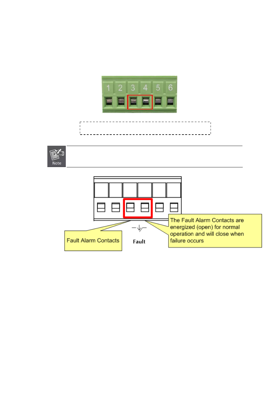
2.2.5 Wiring the Fault Alarm Contact
The fault alarm contacts are in the middle of the terminal block connector as the picture shows below. Inserting the wires,
the Industrial Switch will detect the fault status of the power failure, or port link failure (available for managed model) and
then forms an open circuit. The following illustration shows an application example for wiring the fault alarm contacts.
Insert the wires into the fault alarm contacts
The wire gauge for the terminal block should be in the range between 12 ~ 24 AWG.
Figure 2-14
Power Fault Alarm trigger description
Advertising
This manual is related to the following products: